CUTMASTER 35, 40mm
SERVICE 5T-2 Manual 0-5118
5T.02 Inspection and Replacement
of Consumable Torch Parts
WARNINGS
Disconnect primary power to the system before
disassembling the torch or torch leads.
DO NOT touch any internal torch parts while
the AC indicator light of the Power Supply is
ON.
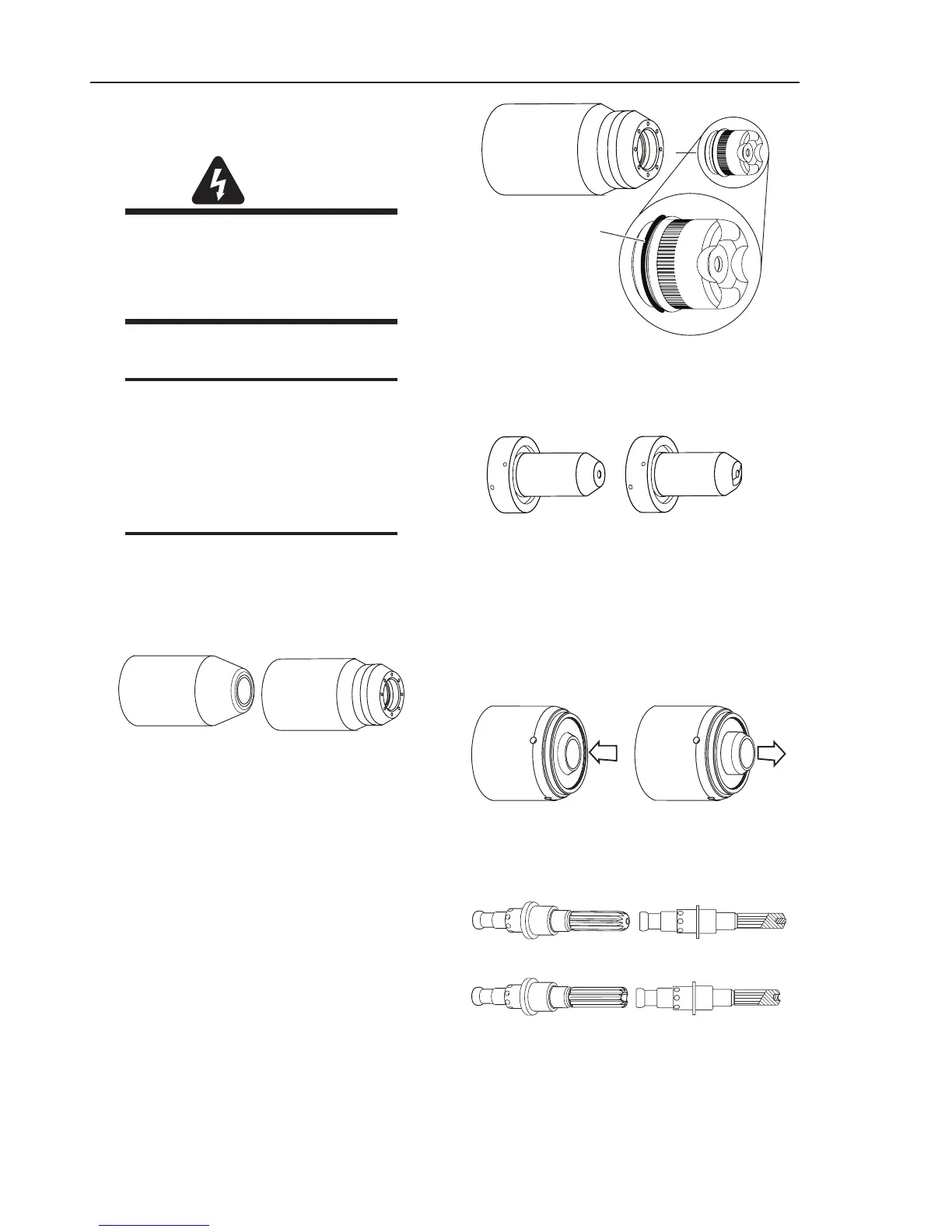
Remove the consumable torch parts as follows:
NOTE
The shield cup holds the tip and starter cartridge
in place. Position the torch with the shield cup
facing upward to prevent these parts from fall-
ing out when the cup is removed.
1. Unscrew and remove the shield cup from the
torch.
NOTE
Slag built up on the shield cup that cannot
be removed may effect the performance of the
system.
2. Inspect the cup for damage. Wipe it clean or
replace if damaged.
Shield Cups
3. On torches with a shield cup body and a shield
cap or deflector, ensure that the cap or deflector
is threaded snugly against the shield cup body.
In shielded drag cutting operations (only), there
may be an O-ring between the shield cup body
and drag shield cap. Do not lubricate the O-
ring.
Drag Shield Cap
Shield
Cup Body
O-Ring No. 8-3488
Art # A-03878
4. Remove the tip. Check for excessive wear (in-
dicated by an elongated or oversized orifice).
Clean or replace the tip if necessary.
Example of Tip Wear
5. Remove the starter cartridge. Check for exces-
sive wear, plugged gas holes, or discoloration.
Check the lower end fitting for free motion.
Replace if necessary.
Art # A-08064
Spring-Loaded
Lower End Fitting
Full Compression 1/8”
Spring-Loaded
Lower End Fitting at Rest /
Full Extension
6. Pull the Electrode straight out of the Torch
Head. Check the face of the electrode for exces-
sive wear. Refer to the following figure.
Worn Electrode
New Electrode
Art # A-03284