CUTMASTER 35mm, 40mm
Manual 0-5118 5-3 SERVICE
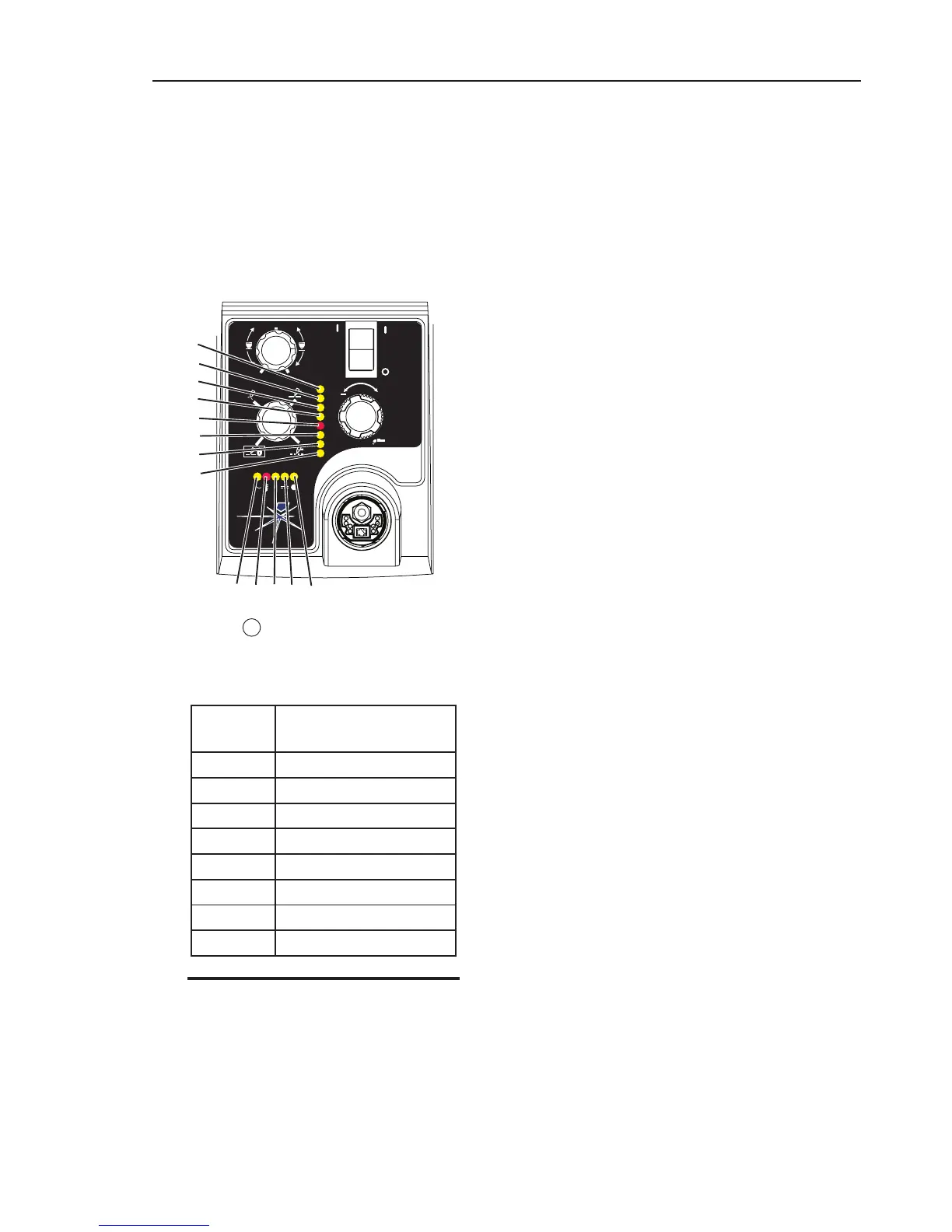
5.04 Fault Indicator
At initial power up, two lights will temporarily illu-
minate for 2-3 seconds to show the version of software
used.
To determine the first digit, count the function indica-
tors left to right, 1 through 5. To determine the second
digit count the pressure indicators, reading from bot-
tom to top, 0 through 7. In the example below the
Temp indicator and 75 psi indicators are on indicating
the version would be 2.3.
"Fault" indicator is on or blinking it
will be accompanied by one of the pressure indi-
cator lights depending on what the Fault is. The
following table explains each of those Faults.
Pressure
Indicator
Fault
Max Over Pressure
90 Internal Error
85 Shorted Torch
80 Consumables Missing
75 Start Error
70 Parts in Place
65 Input Power
Min Under Pressure
NOTE
Fault explanations are covered in the following
tables.