SERVICE TROUBLESHOOTING 28 Manual 0-2569
is greater than +4 vdc (and the TEMP indicator is
lit red), replace the LED PC board. If the voltage
at J3-4 is less than 4V, replace the Logic PC Board.
G. Pressure Sensing Circuits
The Merlin 6000 uses only a plasma gas pressure switch,
PS1, set for 35 psi (2.4 bar) and is located in the power
supply.
1. Check the dc voltage on the logic PCB from TP1
(ground) to J1-7. With the plasma gas pressure set
correctly (refer to Torch Manual for settings) and
the plasma gas flowing, the voltage should be less
than 1 vdc.
• If voltage is correct, proceed to next step.
• If voltage is incorrect, problem is open connec-
tion between Logic PCB and pressure switch,
faulty pressure switch or blockage in the gas
lines between the pressure gauge and pressure
switch (PS1).
2. Check dc voltage from TP1 (ground) to J3-3.
• If voltage is greater than 12 vdc replace the Logic
PCB.
• If voltage is less than 12 vdc, replace the LED
and Current Control PCB or the ribbon cable.
H. Gas Solenoid Circuits
The Merlin 6000 has three groups of solenoids located on
the Rear Panel of the Merlin 6000 Power Supply. Listed
below are their reference designator, function and coil re-
sistance.
1. Standard Gas Select Solenoids
Solenoid Description Ohms (Approx.)
SOL1 Plasma 375
SOL2 Secondary 375
SOL3 Secondary Water 375
SOL1 is on when any gas set mode is selected (Plasma
or Secondary Set).
SOL2 is on for Secondary Set Mode .
During cutting, both SOL1 & SOL2 are on from Start
to the end of Post-flow (Pre-flow, Pilot, Cut & Post-
flow).
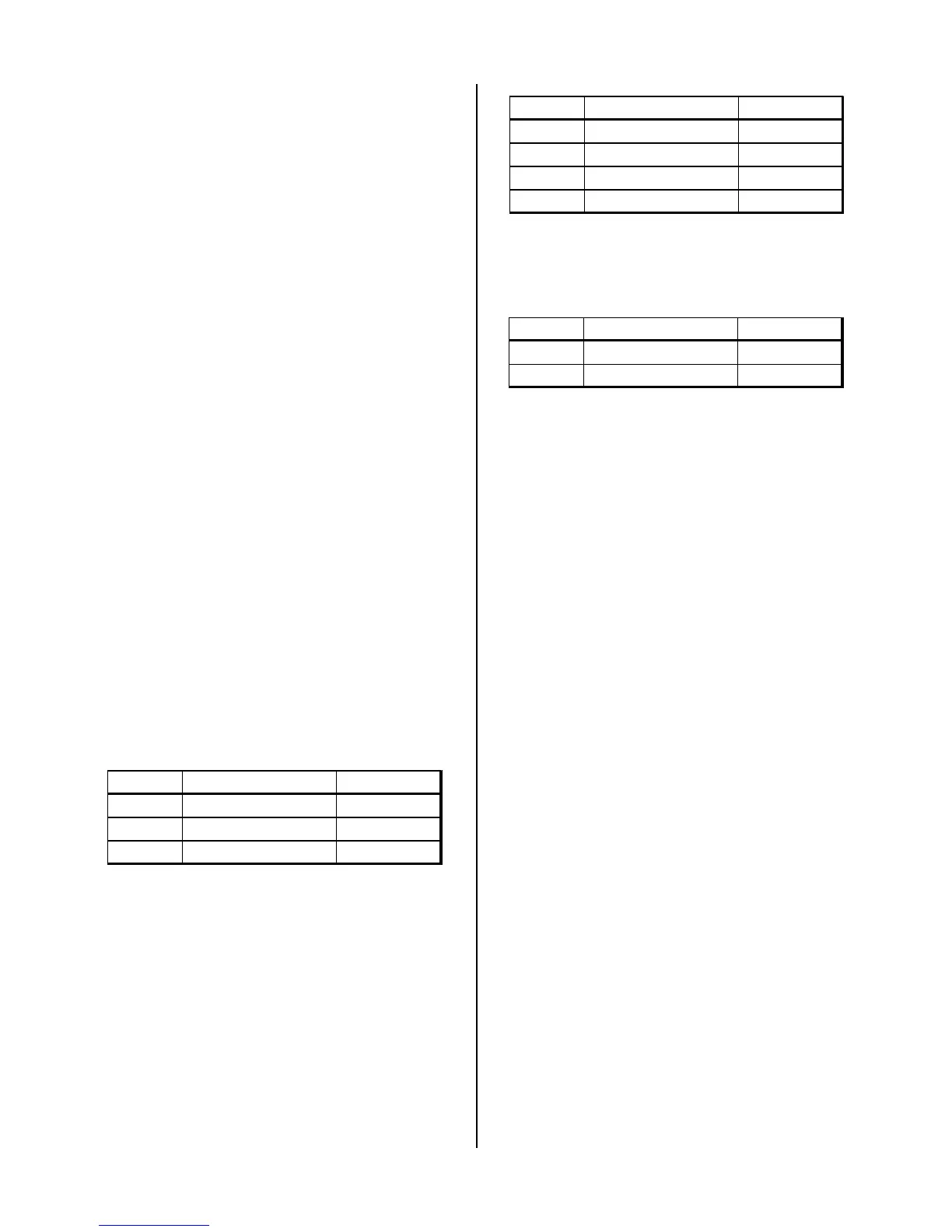
2. Optional Plasma Gas Select Solenoids
Solenoid Description Ohms (Approx.)
SOL4 Air Plasma 300
SOL5 Nitrogen Plasma 300
SOL6 Oxygen Plasma 300
SOL7 Argon/Hydrogen Plasma 300
Normal operation is for one plasma gas solenoid to
be ON when ever the power supply is ON.
3. Optional Secondary Gas Solenoids
Solenoid Description Ohms (Approx.)
SOL8 Nitrogen Secondary 300
SOL9 Other Secondary 300
Normal operation is for one secondary gas solenoid
to be ON when ever the power supply is ON.
For the following tests refer to Appendix XVI, Power Sup-
ply Plumbing Diagram and either Appendix XXIII or
XXIV, System Schematics.
• Plasma Gas Problems Without Optional Gas
Control (GC3000)
Plasma gas passes through the plasma gas solenoid
(SOL1) at the rear panel of the power supply. Low or
no pressure on the Plasma Pressure Gauge can indi-
cate a problem with the plasma gas solenoid, regula-
tor, clogged torch head and leads or the gas supply.
Low or no flow of plasma gas in SET Mode. Make the
following checks:
a. Check that the incoming plasma gas pressure is
correct.
b. With power removed from the power supply re-
move the plasma gas connection at the power sup-
ply bulkhead. Turn ON the power supply and set
the RUN/PURGE/SET switch to the SET position.
If there is a strong gas flow the torch head or leads
are clogged. If there is a weak or no gas flow the
solenoid is faulty.
c. Measure the plasma gas solenoid (SOL1) coil re-
sistance, if it’s not about 375 ohms replace the so-
lenoid. If resistance is correct measure for 120 VAC
across the solenoid coil, if correct the plunger is
stuck, replace the solenoid.
d. If there is no voltage, use Appendix XXIII or XXIV,
System Schematics, to troubleshoot.
SOL1 is controlled from the plasma relay, K4, on
the Logic PCB. To test for a bad Logic PCB, mea-
sure for 120 VAC between wire #9 on the ON/
OFF switch (SW1) and J2-3. If no voltage is there,
 Loading...


