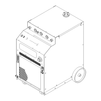
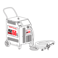
EasyManuals Logo

Thermal Dynamics MERLIN 6000 Service Manual

Thermal Dynamics MERLIN 6000
112 pages
To Next Page IconTo Next Page
To Previous Page IconTo Previous Page
Page #95 background imageLoading...
Page #95 background image
Manual 0-2569 89 APPENDIX
APPENDIX XII: CURRENT CONTROL AND DISPLAY
DIAGRAM
CSD
Output AMPS
Adjustment
Remote Control (RC6010)
Master Power Supply
Demand Signal
3.3 - 10 VDC
to PWM Circuits
J37-5
J37-25
J37-21
J15-20
J15-22
J15-1
3.3 - 10 VDC
(86)
(32)
(97)
J50-8
J50-6
J7-17
Remote Control Cable
Remote Pot High
10 VDC
Switching Control PCB
Remote Demand
3.3 - 10 VDC
Remote Pot Low
3.3 VDC
Pot High 10 VDC
Pot Low 3.3 VDC
J10-17
J10-15
J10-13
J5-17
J5-15
J5-13
LED and Current
Control PCB
J37-11
J37-12
J37-1
J37-2
DISPLAY
150/300A
J15-26
J15-27
J15-3
J15-4
Shunt Amp PCB
J11-5
J11-6
J9-5
J9-6
J7-20
J7-19
J7-2
J7-1
Averaging
Circuit
Remote Installed
J11-6
Shunt Amp PCB
J11-5
Slave Power Supply
J9-5
J9-6
Switching Control PCB
Analog
Analog
Preview
Cut
J70-8
J70-6
J70-10
J70-12
J7-10 J7-11 J50-3
J50-4
J71-14
J71-13
J71-11
J71-10
J54-9
J54-8
J54-1
J54-2
J15-4
J15-3
J15-2
J15-1
J7-1 J7-2
J7-17 J7-18
Parallel Cable
Demand to Slave
3.3 - 10 VDC
to PWM Circuits
(36)
(37)
(34)
(35)
A-02034

Table of Contents

Other manuals for Thermal Dynamics MERLIN 6000

Questions and Answers:

Question and Answer IconNeed help?

Do you have a question about the Thermal Dynamics MERLIN 6000 and is the answer not in the manual?

Thermal Dynamics MERLIN 6000 Specifications

General IconGeneral
BrandThermal Dynamics
ModelMERLIN 6000
CategoryWelding System
LanguageEnglish

Related product manuals