REPLACEMENT PROCEDURES 44 Manual 0-2569
WARNING
Disconnect primary power from the source before
opening or disassembling the power supply. Make
sure AC indicator on the Power Supply front panel
is OFF.
Before disassembling any part of the Power Supply first
read the procedure for the part to be replaced, then pro-
ceed with the disassembly.
5.04 External Parts Replacement
NOTE
Refer to Section 6.03, External Power Supply Re-
placement Parts, for parts list and overall detail
drawing.
A. Left/Right Side Panel Replacement
The Left and Right Side Panels are replaced in the same
manner. The Left Side Panel of the Supply is the panel
on the left side of the unit as viewed from the front of the
unit.
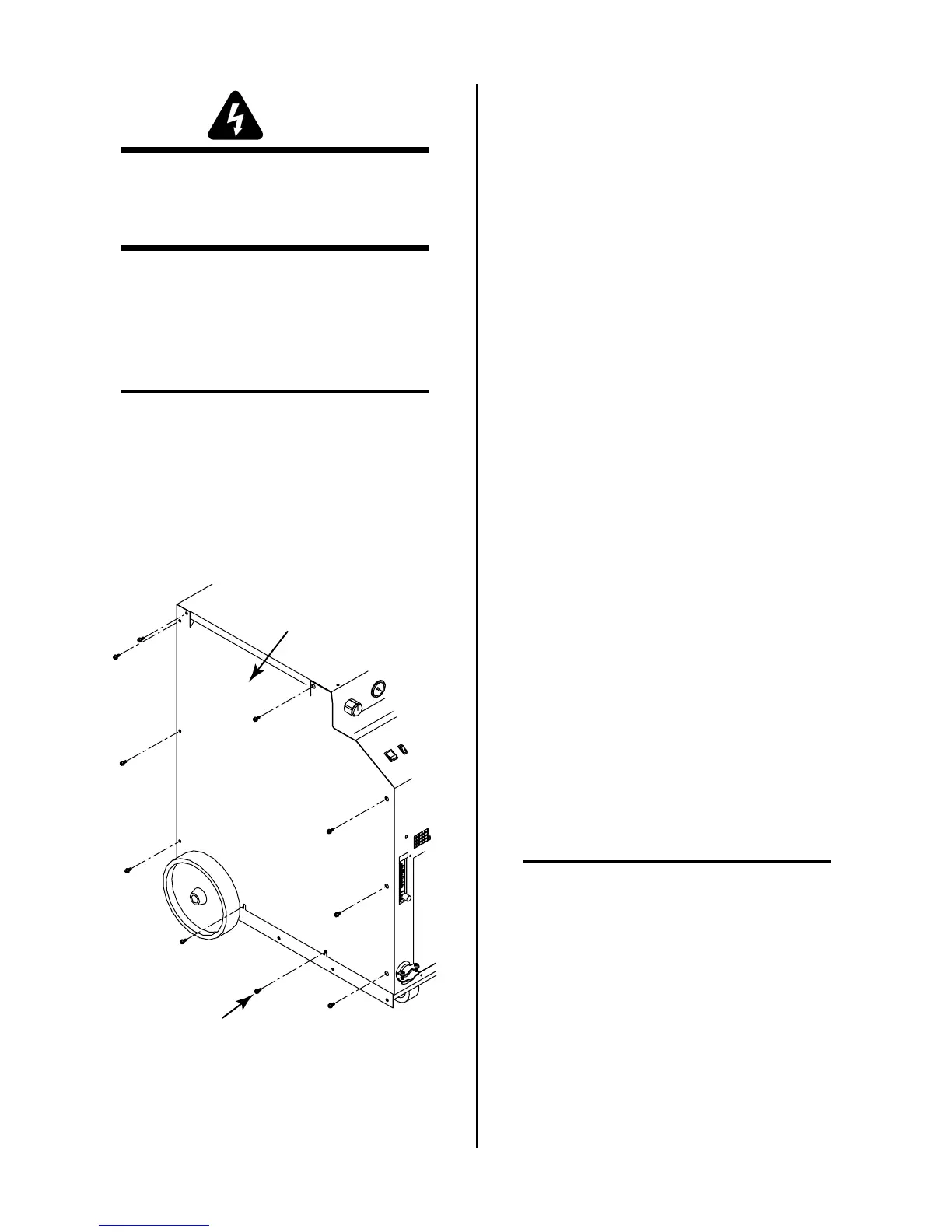
Left Side Panel
Screws
(10 Places)
A-01535
1. Remove the four screws that secure the rear of the
Side Panel to the Power Supply.
2. Loosen the two screws securing the bottom of the
Side Panel to the base of the Power Supply. These
two screws are in slotted holes in the Side Panel.
3. To remove the Side Panel from the Power Supply
pull up and out on the Side Panel.
4. Reinstall the replacement Side Panel by reversing
the above procedure.
B. Top Panel Replacement
1. Remove the Left and Right Side Panels per para-
graph 'B' above.
2. On the top of the unit remove the Coolant Tank
Cap from the Coolant Tank.
3. Remove the four screws securing the Top Panel to
the front of the unit.
4. Remove the two screws securing the Top Panel to
the rear of the unit.
5. Install the replacement Top Panel by reversing the
above procedure.
C. Work Cable Replacement
1. Remove the Left Side Panel per Section 5.04-A.
2. Loosen the two screws of the Work Cable strain
relief securing the Work Cable at the Front Panel.
3. Remove the nut (under the Horizontal Chassis
Panel) securing the Work Cable connection to the
Shunt Assembly.
4. Pull the Work Cable from the unit.
5. Install the replacement Work Cable by reversing
the above procedure.
5.05 Access Panel Parts
Replacement
NOTE
Refer to Section 6.04, Access Panel Replacement
Parts, for parts list and overall detail drawing.
A. CURRENT Knob Replacement
1. Turn the CURRENT adjustment fully counter clock-
wise and note the location of the pointer on the
knob.
2. Loosen the screw securing the Current Knob to the
potentiometer shaft.
3. Remove the old knob.

 Loading...