Manual 0-2569 49 REPLACEMENT PROCEDURES
NOTE
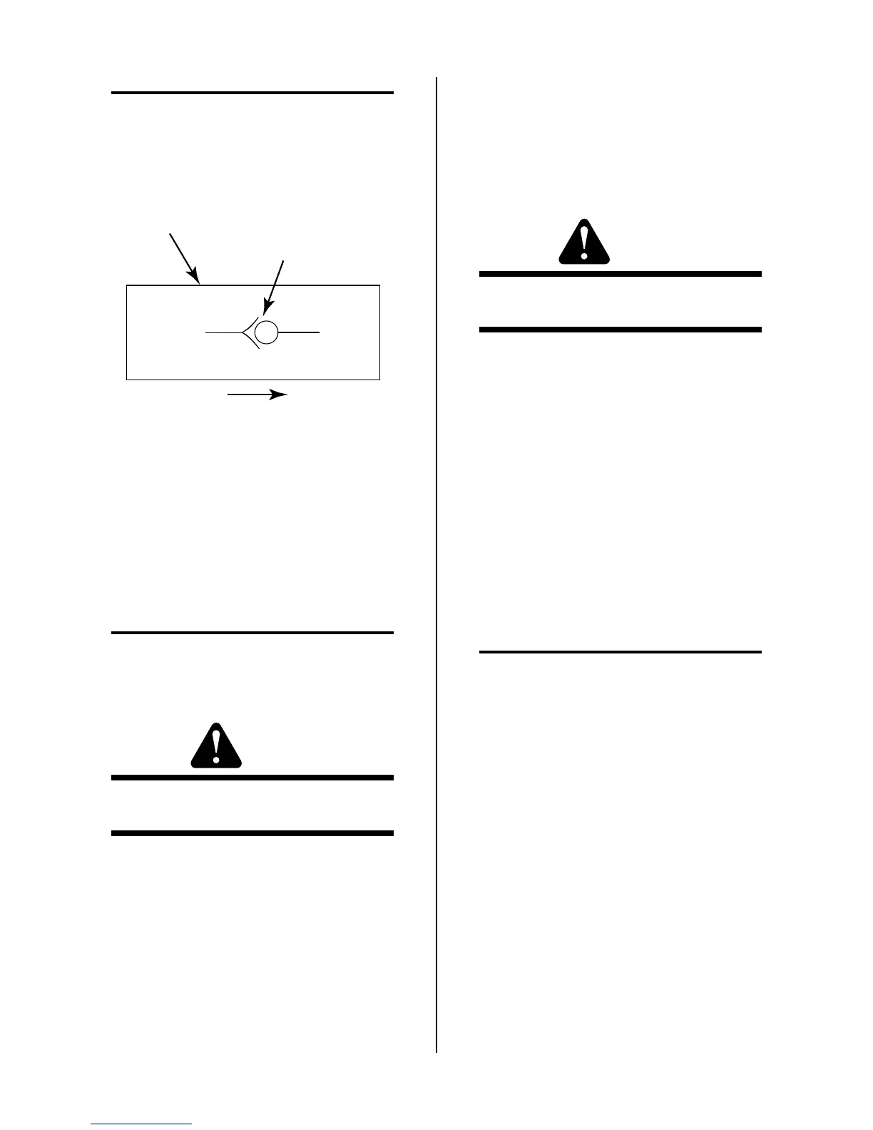
The output of the replacement Check Valve should
be pointing towards the rear of the unit when in-
stalled. The output is designated by a symbol on
the side of the part as shown in the following Fig-
ure.
Symbol
Direction Of Flow
Check Valve
A-00370
4. Install the replacement Check Valve by reversing
the above procedure and noting the following:
• Coat the threads of the Elbow Fitting with a teflon
sealer before installing the replacement Check
Valve.
5.08 Base Assembly Parts
Replacement
NOTE
Refer to Section 6.07, Base Assembly Replacement
Parts, for parts list and overall detail drawing.
A. DC Inductor (L2) Assembly Replacement
WARNING
The removal of this Assembly requires the use of a
mechanical lift.
1. Remove the Left and Right Side Panels per Section
5.04-A.
2. Disconnect all the wiring at the DC Inductor As-
sembly.
3. Remove the six mounting bolts securing the DC
Inductor Assembly to the Base.
4. Place a mechanical lift next to the left side of the
Power Supply.
5. Carefully slide the DC Inductor Assembly out the
left side of the unit and onto the mechanical lift.
6. Install the replacement DC Inductor Assembly by
reversing the above procedure
B. 29KVA Transformer (T1) Assembly
Replacement
WARNING
The removal of this Assembly requires the use of a
mechanical lift.
1. Remove the Left and Right Panels per Section
5.04-A.
2. Disconnect all the wiring at the Transformer As-
sembly.
3. Remove the six bolts, star washers and flat wash-
ers securing the Transformer Assembly to the Base.
4. Place a mechanical lift next to the left side of the
Power Supply.
5. Carefully slide the Transformer Assembly out the
left side of the unit and onto the mechanical lift.
6. Install the replacement Transformer Assembly by
reversing the above procedure.
C. Main Contactor (W1 or W2) Replacement
NOTE
The Main Contactors, W1 and W2, are replaced in
the same manner.
1. Depending on which Main Contactor Assembly is
to be replaced, remove the Left or Right Side Panel
per Section 5.04-A.
2. Label all the wiring connected to the Main Contac-
tor Assembly.
3. Disconnect the wires from the Main Contactor As-
sembly terminals.
4. Remove the two screws and star washers securing
the Main Contactor Assembly to the Base.
5. Install the replacement Main Contactor Assembly
by reversing the above procedure.
D. Motor (M1) Assembly Replacement
1. Remove the Left and Right Side Panels per Section
5.04-A.
 Loading...


