SERVICE TROUBLESHOOTING 32 Manual 0-2569
nal. The signal goes to the Slave Power Supply
Logic PCB. Check for 0 vdc from TP1 (ground) to
J4-9 on the Logic PCB.
• If the voltage is correct and the TEMP LED is green
the Slave Power Supply Logic PCB is faulty.
L. Remote Control Start Circuit
NOTE
Refer to Appendix XI for Start Circuit Diagram.
The start signal from the cutting machine controller en-
ters the RC6010 at J29 or J6 and may be either a momen-
tary closure (J29-1) or sustained closure (J29-3). It passes
through optical isolation circuits and, if the ENABLE is
on and the station select input is active, lights internal
led D103. If the Standoff Control (SC10) is not used, start
goes to the remote cable at J37-9.
If the Standoff Control (SC10) is connected, then the start
signal goes to it, active low at J5-13, lights internal indi-
cator D79 and starts the find height sequence. Once height
is found the front panel PLASMA ON inicator comes ON.
If FIND HT is not ON, the find height function is by passed
and PLASMA ON comes on immediately. The start sig-
nal then is returned to the Remote Control (RC6010), ac-
tive low on J7-17, and to the remote cable on J37-9 to the
Power Supply remote connector J15-24 and TB2-3 and
on to the Power Supply Logic PC Board.
If the Standoff Control (SC10) is installed and the system
won’t find height the problem is in the Standoff Control
(SC10), Remote Control (RC6010) or the interconnections
to the cutting machine. Set FIND HT off, it the torch starts
now the problem is in the Standoff Control (SC10).
NOTE
Refer to Section 5, Customer/Operator Service, in
the Standoff Control Instruction Manual.
If it doesn’t start, open the cover of either the Standoff
Control (SC10) or Remote Control (RC6010), whichever
one is on top, and disconnect the ribbon cable at J5 or J7.
Then if the Power Supply will start the problem is in the
Standoff Control (SC10) or the ribbon cable. Refer to
Section 5, Customer/Operator Service, in the Standoff
Control Instruction Manual.
If the Standoff Control (SC10) isn’t used or the Power
Supply didn’t start with the ribbon cable disconnected,
there are two approaches you can take. Either discon-
nect the remote and see if the Power Supply will start
without it or check if the start signal is getting to the Re-
mote Control (RC6010). To check the Power Supply, re-
move the remote connector at J15 and connect a jumper
TB2-1 to TB2-2 for ENABLE, then jump TB2-3 to TB2-4
for start. If it starts the problem is in the remote or CNC
connections. If not refer to Section 4.05-K, Power Supply
Start Circuit.
To check for start to the Remote Control (RC6010), open
the Remote Control cover and see if indicator D103 comes
ON. If so, problem is in Remote control (RC6010) or the
remote cable. If indicator D103 is OFF, remove J29 (or
the CNC start connections to J6) and jumper J29-3 to 4 or
J6-3 to 4. Don’t jumper to the screw heads on J6 as they
don’t always make electrical contact. If it starts (indica-
tor D103 ON) with the jumper, the problem is in the CNC
connections. If not, replace the Remote Control (RC6010).
M. Switching Control Check (Q1)
To produce DC output, the main switch (Q1) must be
turned on and off rapidly. Power Supply output is con-
trolled by the on-time. At the same time the Main Con-
tactor (W1 or W2) closes, the Logic PC Board grounds
pins 9 and 23 of the 34-pin ribbon cable (J3-9 on the Logic
PC Board, J10-9 on the Switching Control PC Board). This
enables the pulse width modulator (PWM) on the Switch-
ing Control PC Board.
If DC voltage is not detected within 75 ms at J1-24 on the
Logic PC Board, the enable signal on J10-9 is removed
and the Main Contactor opens. Connecting TP4 to TP1
(ground) on the Logic PC Board disables this function for
troubleshooting if no DC output is found.
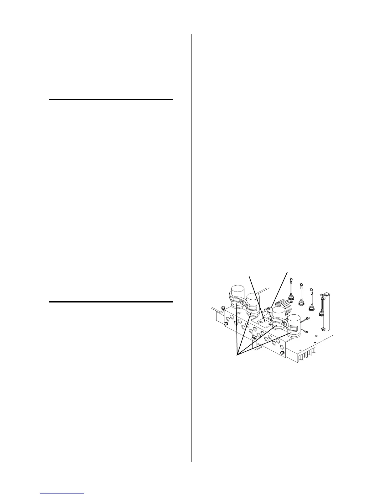
Switching Transistor
Q1
Large Blue
Capacitors
A-01085
Transistor/Coil
Bracket
Q1 Location
To check for a defective Q1, first disconnect J27 from
the Driver PC Board.
 Loading...


