17
CUSTOMER/OPERATOR SERVICE
Manual 0-2577
SECTION 4: CUSTOMER/OPERATOR SERVICE
4.1 POWER SUPPLY SPECIFICATIONS
Controls
Panel Indicators
Input Power
Output Power
OCV
Duty Cycle
Work Lead
Cut Capacity
Pilot Circuitry
Gas Connection
Weight
• ON/OFF Switch
• RUN/SET Switch
• Output Current Control
• Pressure Regulator Control
LED Indicators: AC Power, GAS, DC, TEMP
Pressure Gauge
110 VAC (±10%), 50/60 Hz, 15 Amp Single Phase
Continuously variable from 12 to 20 Amps maximum
375 VDC
40%
10 ft (3 m) with clamp
1/4 in (6.4 mm) Steel
Capacitor Discharge (CD), Pulsed DC
Front panel entry 1/4 NPT
42.5 lbs (19.3 kg)
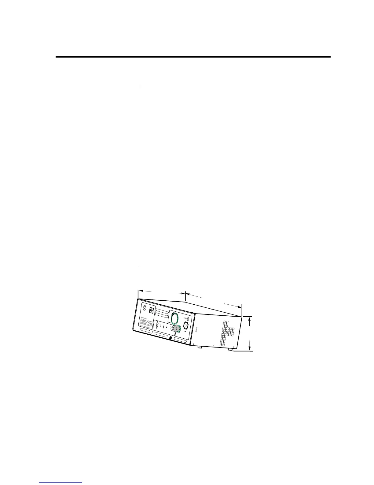
Figure 4-A Power Supply Dimensions
17.5 in
(445 mm)
13.25 in
(337 mm)
7.5 in
(191 mm)
A
C
P
O
W
E
R
I
N
P
U
T
P
O
W
E
R
P
R
E
S
S
U
R
E
T
O
R
C
H
W
O
R
K
O
PERATING
PRESS
URE
50 PSI
(3.4 BAR
)
C
U
R
R
E
N
T
R
U
N
S
E
T
A
C
G
A
S
D
C
1
2
2
0
M
a
d
e
in
t
h
e
U
S
A
R
R
A-01293
Note:
Handle Not Shown