25
CUSTOMER/OPERATOR SERVICE
Manual 0-2577
WARNING
Replacing the
PIP Assembly
CAUTION
Disconnect primary power to the system before disassembling
the torch, leads, or power supply.
Refer to Figure 4-F and:
1. Carefully remove the PIP wires from the strain relief bosses
inside the split holder.
2. Slide the PIP pin receptacles forward out of the retention
slots.
Do not lift the PIP pin receptacles out of the split holder. Dam-
age to holder and/or PIP pin receptacles may occur.
3. Install replacement PIP pin assemblies by positioning the
square solder post of the PIP pin receptacle in the retention
slot in the split holder and sliding the assembly up into place.
Position the flange on the PIP pin receptacle flush with the
front face of the split holder.
4. Route the PIP wires around the strain relief bosses as shown.
Push the teflon insulation on each PIP wire up to the strain
relief boss closest to the back of the split holder for voltage
insulation from the brass pilot lead connector.
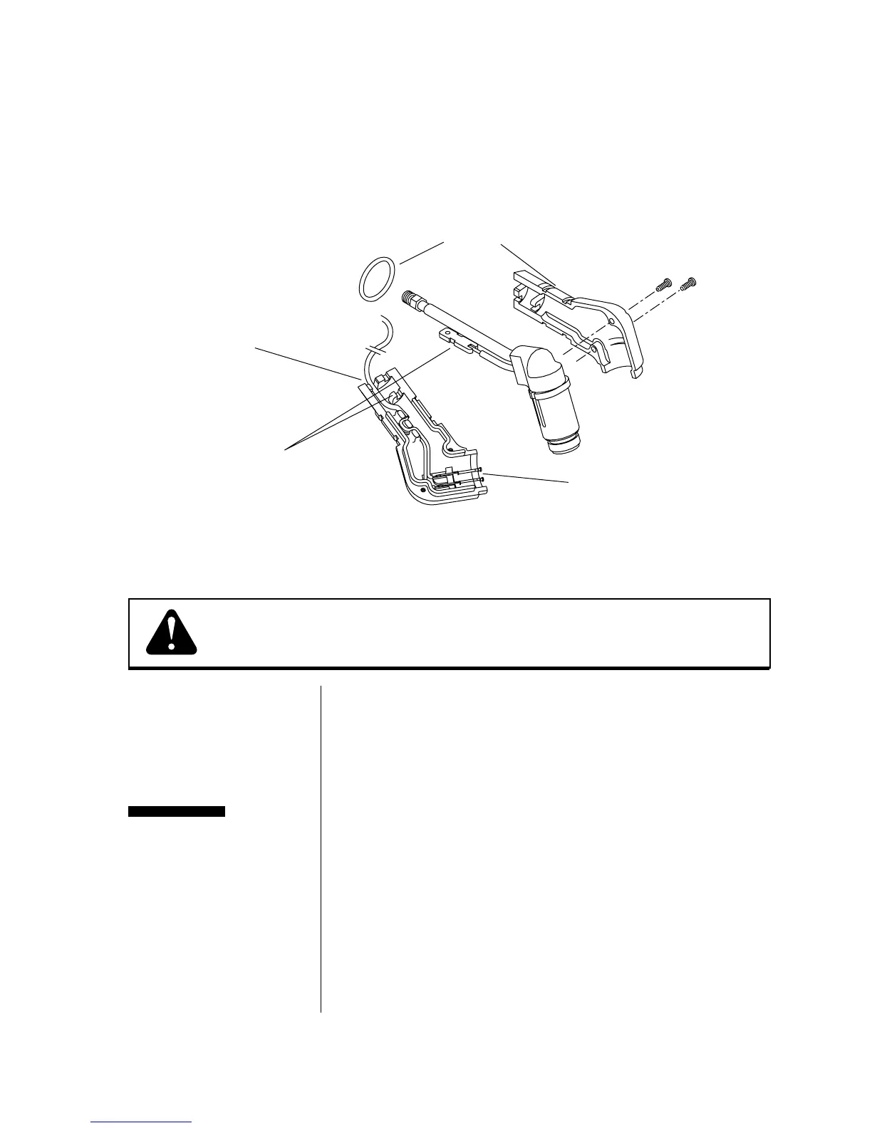
Figure 4-E Disassembling the Split Holder
PIP Pin Assemblies
Position PIP wires
in notches in back
of split holder
Align notch on
pilot lead with
notch in split holder
Handle O-Ring
(position in rear groove)
Mounting Screws
A-00782