26
CUSTOMER/OPERATOR SERVICE
Manual 0-2577
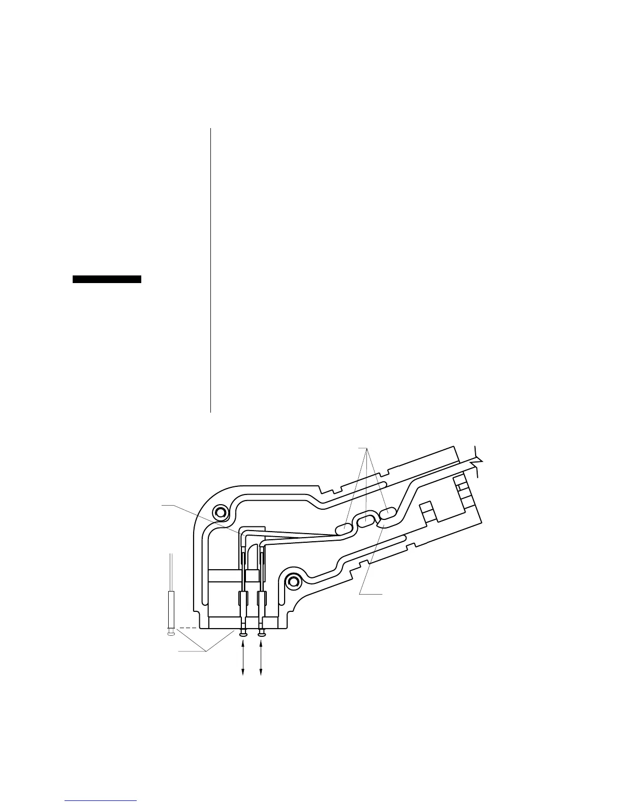
Figure 4-F Installing a Replacement PIP Assembly
5. Position both PIP leads through the notch where the nega-
tive/plasma lead exits the holder.
6. Position the torch head inside the holder. Align the notch on
the pilot lead with the corresponding tab on the split holder.
Make sure the negative/plasma fitting is securely inserted in
the groove in the holder. Make sure the crescent on the torch
head is inserted into the mating groove in the holder.
7. Place the second half of the holder over the torch head.
Confirm that the PIP pin assemblies, PIP leads, and the
negative/plasma and pilot leads are properly positioned.
Do not force the holder together. Damage to the insulation on the
leads will cause torch head failure. The PIP leads must be posi-
tioned correctly to allow reassembly of the torch head.
Refer to Figure 4-E and:
1. Install the two assembly screws to secure the split holder and
reinstall the O-ring in the rear groove on the back of the torch
head assembly.
Refer to Figure 4-C and:
2. Install the front end torch parts.
Replacing the
PIP Assembly
(continued)
CAUTION
Reassembling
the Torch Head
Remove and install PIP assemblies
from the front. Position assemblies
in slots in split holder.
Teflon wire coating
must cover wire up
to strain relief area.
Position PIP wires
through strain relief
bosses as shown
Position flange
on PIP receptacle flush
with face of split holder.
Bend wires to
fit grooves
AB
Install wire A first, then wire B.
A-00783