INSTALLATION 16 Manual 0-2470
3.03 SETTING UP THE TORCH (continued)
WARNING
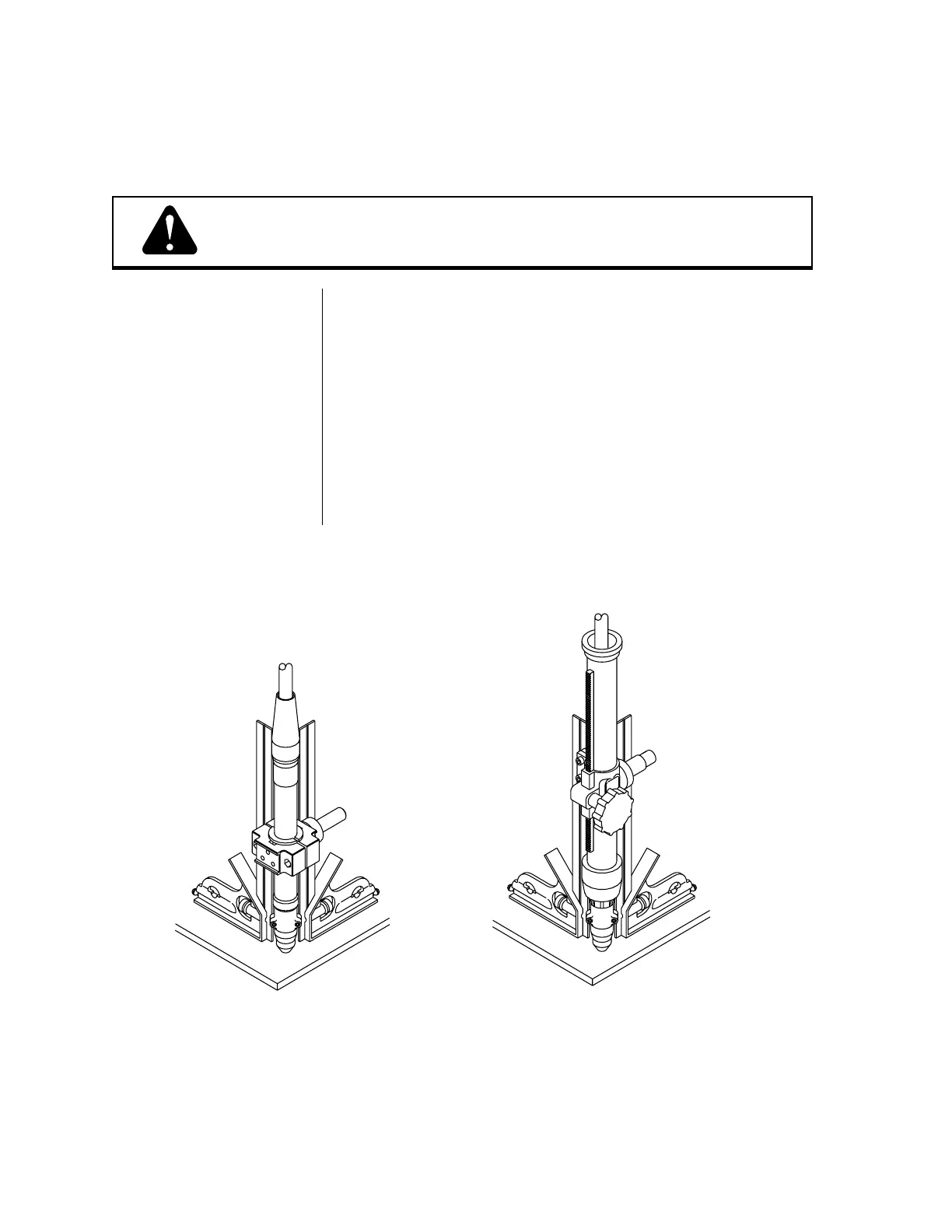
Machine Torch Set-Up
Figure 3-B Machine Torch Set-Up
Disconnect primary power at the source before disassembling
the power supply, torch, or torch leads.
The torch parts (shield cup, tip, electrode, and gas distributor)
must correspond with the type of operation (drag cutting, stand-
off cutting, or gouging). Refer to Torch Parts Selection (page 23).
Metal mounting tubes with rack and pinion assemblies are
standard for machine torches. Phenolic (plastic) mounting tubes
with pinch blocks are optional (see Torch Options and Accesso-
ries, page 80).
1. Mount the torch assembly on the cutting table.
Refer to Figure 3-B and:
2. To obtain a clean vertical cut, use a square to align the torch
perpendicular to the surface of the workpiece.
Use a square to align
the torch assembly
perpendicular to the surface
of the workpiece
Shown wth
Phenolic Pinch
Block Mounting
Assembly
A-00057
Shown with
Rack and Pinion
Mounting Assembly