Manual 0-2470 15 INSTALLATION
3.03 SETTING UP THE TORCH
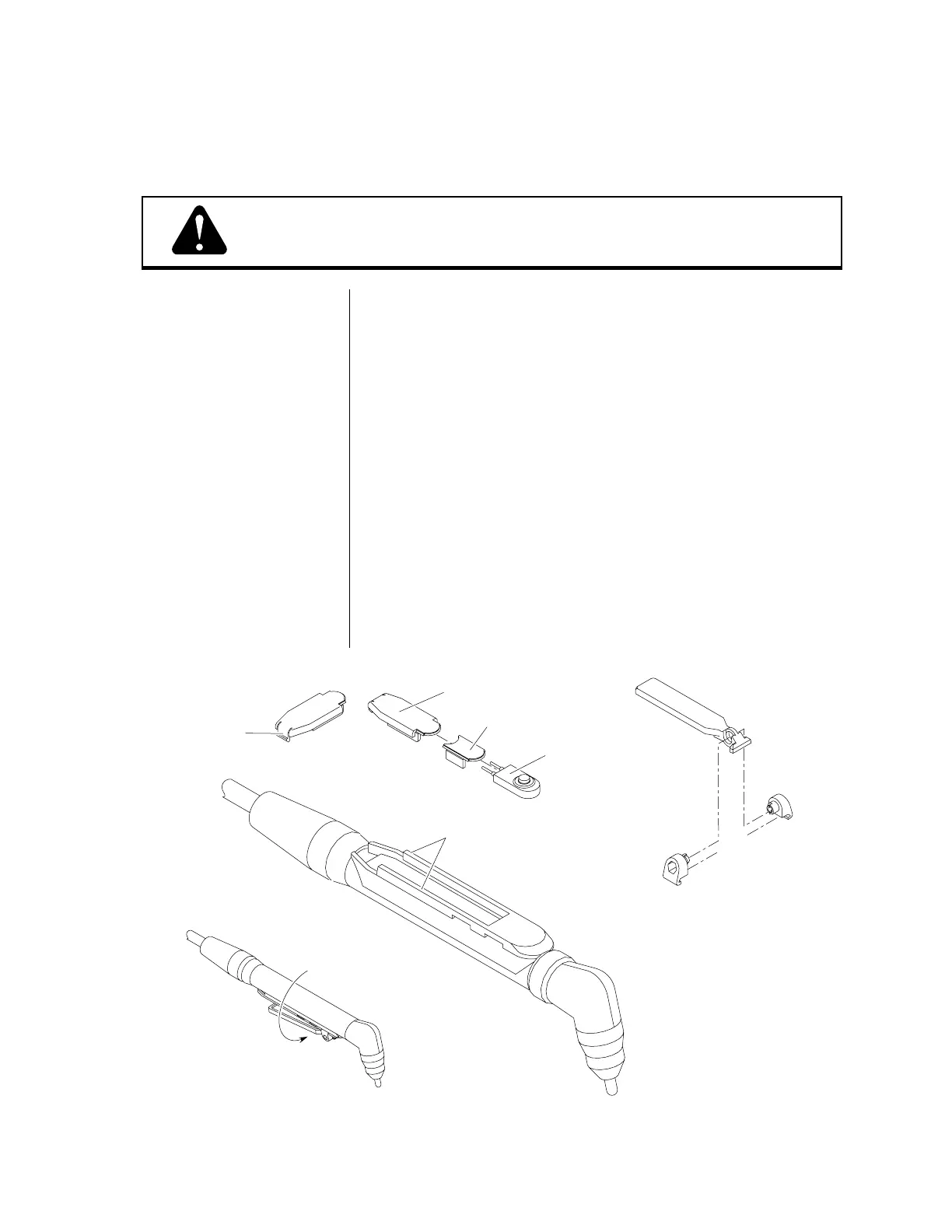
Figure 3-A Hand Torch Switch Options
WARNING
Hand Torch Set-Up
Disconnect primary power at the source before disassembling
the power supply, torch, or torch leads.
The torch parts (shield cup, tip, electrode, and gas distributor)
must correspond with the type of operation (drag cutting, stand-
off cutting, or gouging). Refer to Torch Parts Selection (page 31).
The torch is factory assembled with the control switch in the top
front position (see Figure 3-A below). To position the control
switch on the bottom (underside) of the handle, pull the handle
back approximately 2 inches (51 mm) and rotate the handle
assembly 180° (do not rotate beyond 180°). To position the
control switch in the rear position:
1. Locate the tab on the back of the switch track closure. Gently
press in on the tab and carefully pry the closure upward.
2. Remove the switch track insert and the torch control switch.
3. Reinstall the switch track insert, then the switch, then the
switch track closure.
The optional switch lever kit provides a lever for activating the
torch control switch. Refer to Torch Options and Accessories
(page 80) for ordering information.
Bottom mounted
torch switch (shown
with optional switch lever)
Switch Track Closure
Switch Track Insert
Switch Assembly
Switch Track
Switch Lever
with Mounting
Brackets
(Optional)
Reverse view of
closure - press
tab to remove