OPERATION 40 Manual 0-2470
4.09 RECOMMENDED CUTTING SPEEDS
Cutting speed depends on material, thickness, and the operator’s
ability to accurately follow the desired cut line. The following
factors may have an impact on system performance:
• Torch parts wear
• Air quality
• Line voltage fluctuations
• Torch standoff height
• Proper work cable connection
This information represents realistic expectations using recom-
mended practices and well-maintained systems. Actual speeds
may vary up to 50% from those shown.
Recommended
Cutting Speeds
NOTE
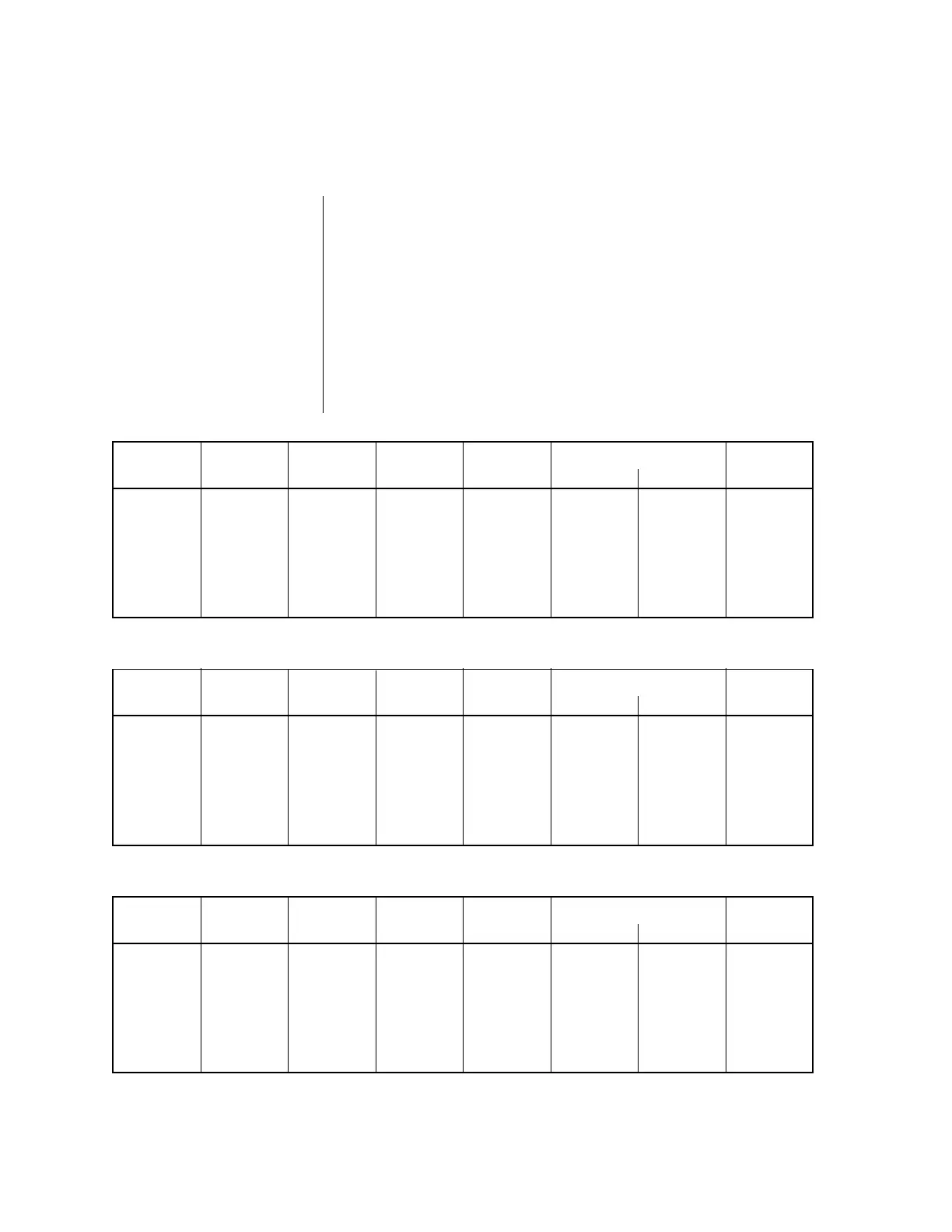
Thickness Tip Gas(es) Voltage Amperage Speed (Per Minute) Standoff
(Inches) (Cat. No.) (Volts) (Amps) (Inches) (Meters) (Inches)
1/16 9-6000 Air 97 35 260 6.6 1/8
1/8 9-6000 Air 102 35 75 1.9 1/8
1/4 9-6000 Air 108 35 45 1.1 1/8
3/8 9-6000 Air 115 35 22 0.6 1/8
1/2 9-6000 Air 120 35 12 0.3 1/8
Table 4-D PCM-35 Cutting Speeds - Air Plasma on Mild Steel
Thickness Tip Gas(es) Voltage Amperage Speed (Per Minute) Standoff
(Inches) (Cat. No.) (Volts) (Amps) (Inches) (Meters) (Inches)
1/16 9-6000 Air 100 35 250 6.3 1/8
1/8 9-6000 Air 118 35 100 2.5 1/8
1/4 9-6000 Air 124 35 25 0.6 1/8
3/8 9-6000 Air 130 35 15 0.4 1/8
1/2 9-6000 Air 136 35 5 0.1 1/8
Table 4-E PCM-35 Cutting Speeds - Air Plasma on Aluminum
Thickness Tip Gas(es) Voltage Amperage Speed (Per Minute) Standoff
(Inches) (Cat. No.) (Volts) (Amps) (Inches) (Meters) (Inches)
1/16 9-6000 Air 110 35 250 6.3 1/8
1/8 9-6000 Air 112 35 75 1.9 1/8
1/4 9-6000 Air 114 35 20 0.5 1/8
3/8 9-6000 Air 117 35 10 0.3 1/8
1/2 9-6000 Air 124 35 7 0.2 1/8
Table 4-F PCM-35 Cutting Speeds - Air Plasma on Stainless Steel