Manual 0-2470 63 CUSTOMER/OPERATOR SERVICE
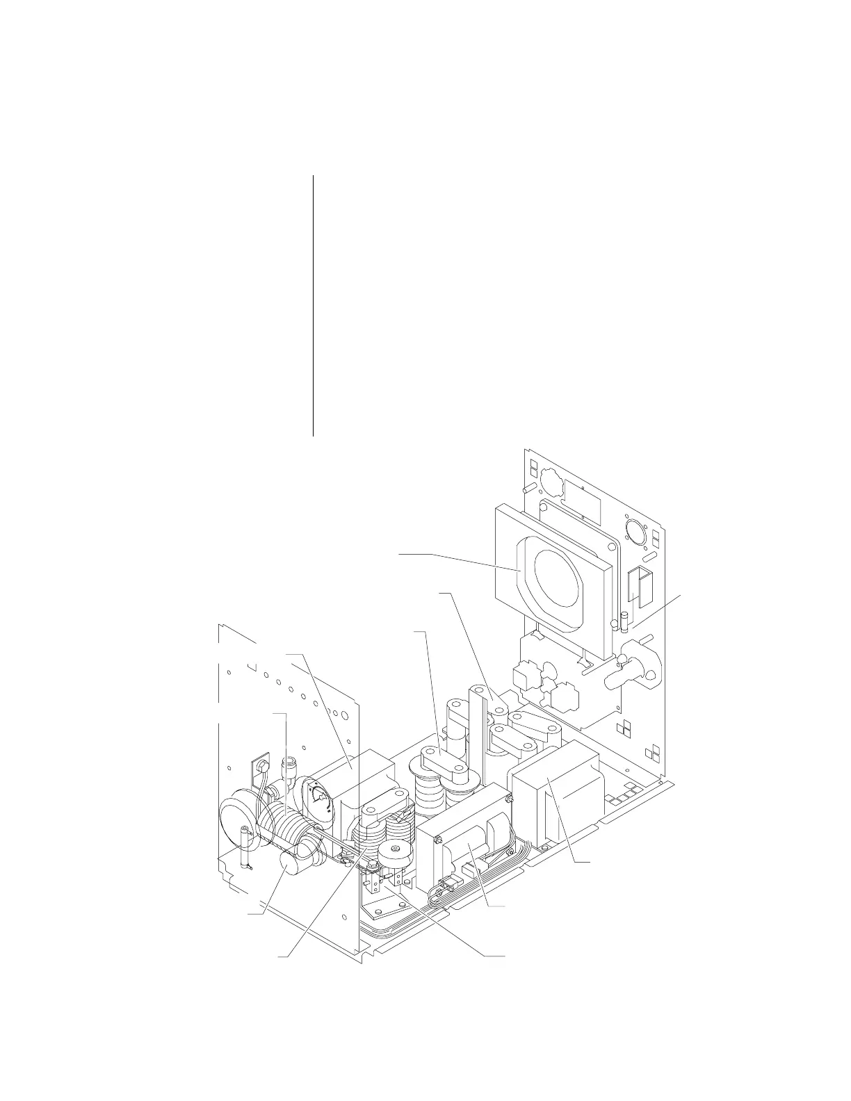
Figure 5-I Base Panel Component Locations
5.08 SERVICE PROCEDURES (continued)
The only reason the pilot inductor should be replaced is if the
cores are cracked due to shipping damage or the unit being
dropped. Minor chips are normal. If any burning or arcing is
visible on the pilot inductor, return the unit to an authorized
service center.
To remove the pilot inductor:
1. Disconnect the wire from one lead of the pilot inductor and
the connecting copper link from the other lead.
2. Turn the unit on its side to access the two mounting nuts and
lockwashers which attach it to the chassis. Remove the
inductor from the unit.
3. Install the replacement inductor by reversing the above
procedure. To avoid damaging the core of the replacement
inductor, do not force it into place.
Pilot Inductor (L4)
Main Transformer (T3)
Pilot Inductor (L4)
Work Lead Inductor (L7)
Inductor Assembly (L6)
Auxiliary Transformer (T1)
High Frequency Transformer (T2)
Spark Gap Assembly
HF Core Inductor (L5)
Fan Assembly
Regulator/Solenoid/
Gauge Assembly
Fuse 1FU
A-00762