Manual No. 0-4819 2-7 SPECIFICATIONS
B. Torch Leads Lengths
Feet Meters
10 3.05
15 4.6
25 7.6
50 15.2
75 22.8
100 30.4
125 38.2
150 45.7
175 53.3
Length
Gas Lead Assemblies
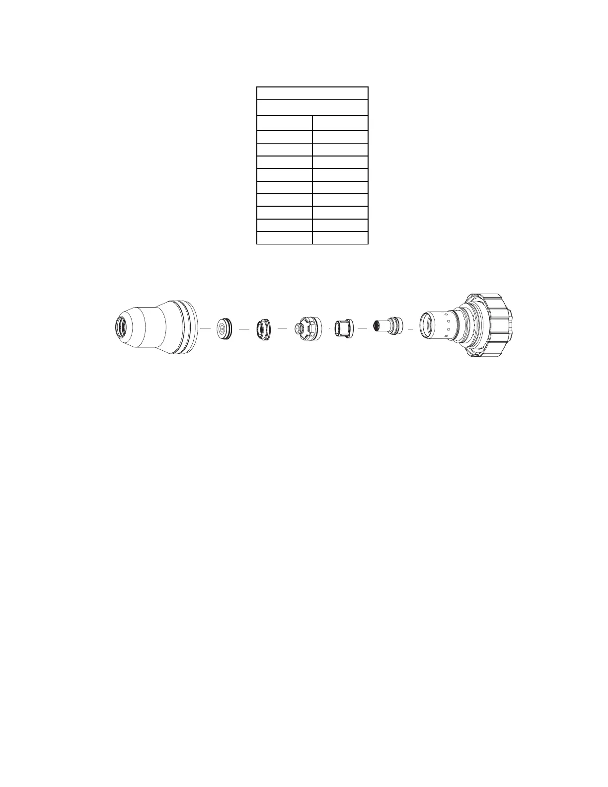
C. Torch Parts (Generic Parts Shown)
Cartridge
Shield Cup
Art # A-04741
Electrode
Tip
Plasma Gas
Distributor
Shield Gas
Distributor
Shield Cap
D. Parts - In - Place (PIP)
The torch is designed for use with a power supply which senses coolant return flow to confirm that torch
parts are in place. If coolant return flow to the power supply is absent or insufficient the power supply will
not provide power to the torch. Coolant leakage from the torch also indicates that torch parts are absent
or installed improperly.
E. Type of Cooling
Combination of gas stream through torch and liquid cooling.
 Loading...


