7-20
Installation
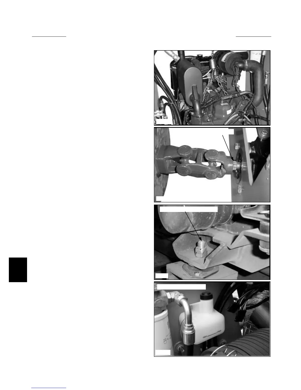
14 Install the engine to the loader. (fig. C3639) Have a
helper inside the cab to line up the engine U- Joint to
the hydrostatic pump input shaft. (fig. C3644) Align the
engine U-Joint in a straight line with the hydrostatic
pump. Failure to align the U- Joint properly will cause
premature U- Joint failure.
C3639
C3625
C3612
C3644
Guide U- Joint onto spline
Torque 80 ft / lbs (109 Nm)
15 Install the engine mounting bolts to the isolators.
Torque the bolts to 80 ft / lbs. (109 Nm).(fig. C3612)
16 Connect the various electrical connections, routing
wires carefully to prevent chaffing. Tie the wires with
Zip ties as required. Be sure all ground point are clean.
17 Install the intake and exhaust systems.
18 Install the coolant over flow tank and hoses. (fig.
C3625)
19 Connect the fuel supply and turn on the fuel tank
petcock.
20 Bleed the air from the fuel lines.
20 Check the engine oil and coolant level.
21 Check again for any loose wires that may be dan-
gling free.
22 Test fire the engine.
Coolant over flow tank
ENGINE REPLACEMENT 7.3