1-22
C2258
C3720
C3722
Disassembly / Repair 175
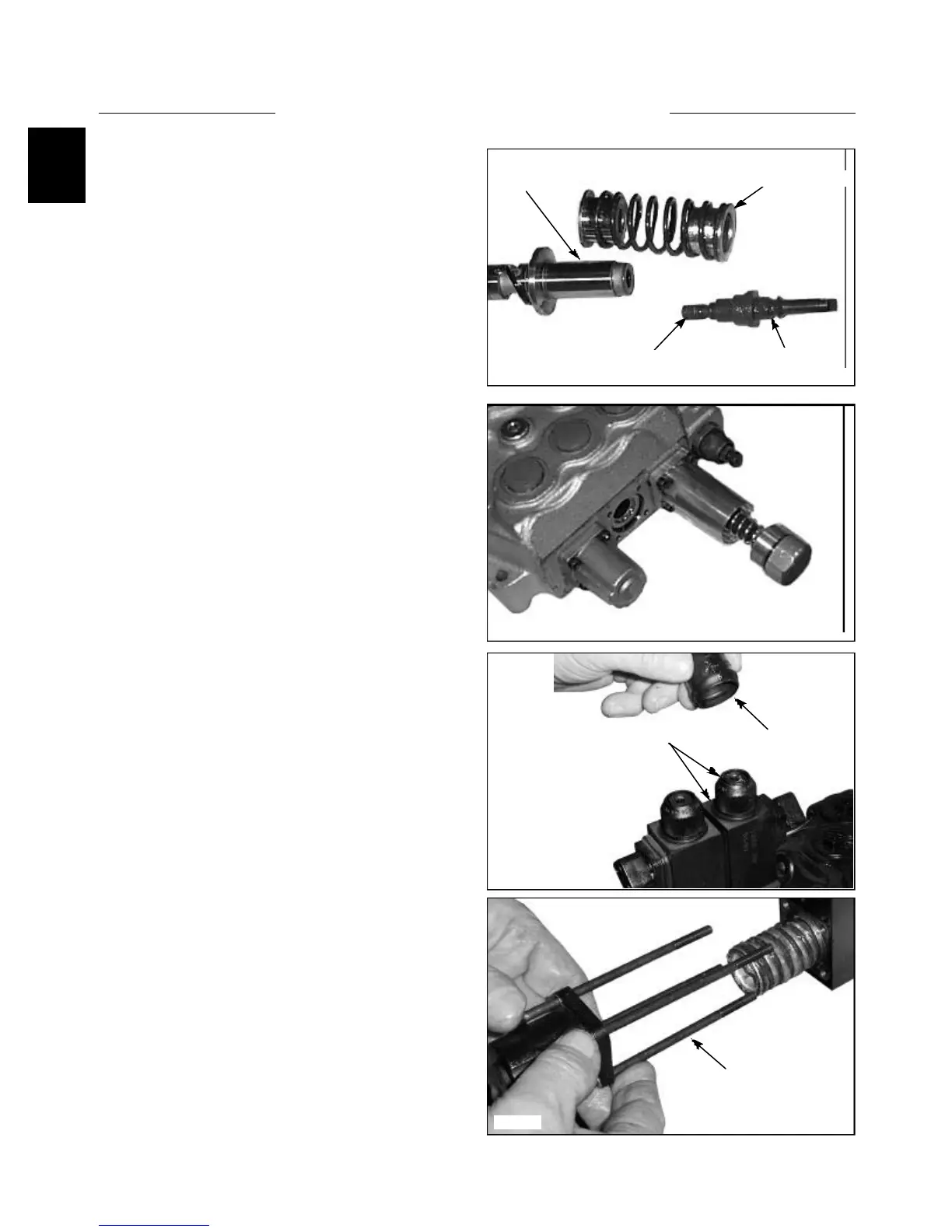
(cont’d)
Solenoid Controlled Auxiliary
1 Remove the rubber boot covering the retaining nut on
top of each solenoid coil.
2 Remove the nut and O-ring and pull off the solenoid
coil (s). (fig. C3720)
3 Remove the screws retaining the solenoid assembly
to the control valve. (fig. C3722). Upon assembly tighten
the screws to 6.6 Nm (4.9lbs / ft).
12 Install the spring return / centering cover and tighten
the mounting screws evenly to 6.6 Nm (4.9 lbs / ft).
Install the end cap to the cover and tighten to 9.8 Nm
(7.2 lbs / ft). (fig. C2258)
CONTROL VALVE 1.3
Detent spring and cap
Nut and O-Ring
Rubber Boot
Screws
11 Install the spring return / centering cover and tighten
the mounting screws evenly to 6.6 Nm (4.9 lbs / ft).
Install the end cap to the cover and tighten to 9.8 Nm
(7.2 lbs / ft). (fig. C2258)
C2238
Spool spring and bushings
Apply Loctite 542
Detent
Detent