2-40
DRIVE MOTOR 2.11
C3532
C3533
C3534
C3535
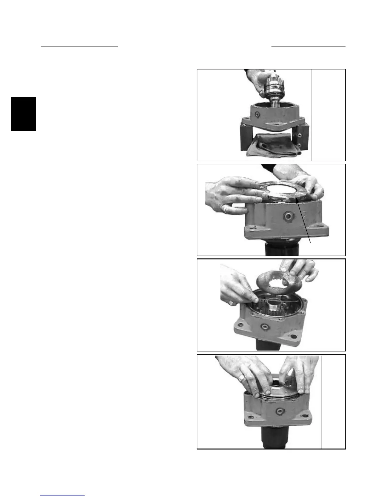
1 The re-assembly of the motor is done opposite of the
dissassembly. Support the housing and install the output
shaft and bearing assembly. (fig. C3532).
Assembly
Install bearing
4 Install the piston after all of the disks have been
inserted. There will be air trapped, but this will escape
when the spring and cover are installed. (fig. C3535)
3 Alternate installation of brake disks, first putting in
the outer disk (golden color) and then the inner disk (sil-
ver color). (fig. 3534)
2 Install bearing retaining ring and tighten with Torx
drive to 7ft/lbs. (fig. C3533)