2-41
DRIVE MOTOR 2.11
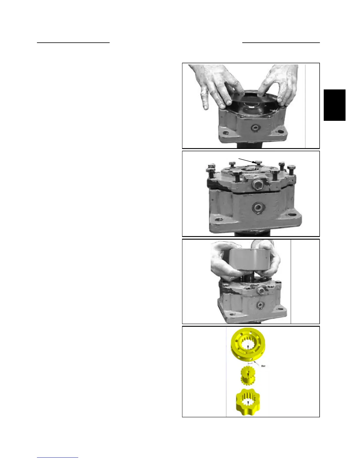
C3536
C3537
C3538
C3539
5 Install spring plate (fig. C3536)
6 Install brake cover and cross tighten all screws to
final torque specification of 65ft/lbs. (fig. C3537)
7 Install Cardon shaft and gearwheel. (fig. C3538)
8 With the gearwheel mounted and the cardon shaft in
place, place the drive gear valley to valley with the gear-
wheel. Mount the channel plate (ensuring the drain holes
are aligned) and then valve drive it 15
o
counter clockwise
(one tooth). Then mount the valve housing and re-install
the bolts. (fig. C3539).
Incorrect timing will result in the motor operating in
reverse.
Screws