1-4
GENERAL INFORMATION 1.1
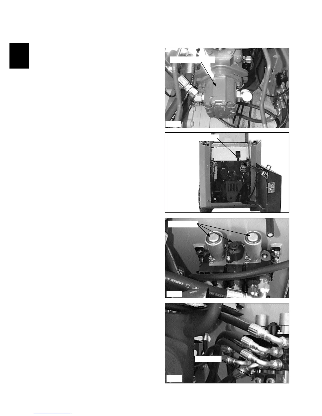
Oil is drawn from the hydraulic oil reservoir through a
100 micron element. From there it travels to the main
hydraulic pump. (fig. C2353).
The hydraulic pump is a gear type which is driven by a
shaft and coupler through the hydrostatic drive pump at
engine speed. The oil then flows from the gear pump to
the hydraulic control valve. (fig. C2347).
The hydraulic control valve is equipped with an
adjustable relief valve which is adjusted to 2150 PSI (148
Bar). The control valve is a parallel type with 3 spools
(banks). The various spools activate the boom, bucket and
auxiliary hydraulic functions.
When the spools are in neutral, oil flows from the
hydraulic gear pump, through the control valve and
returns to the 10 micron hydraulic filter. From the
hydraulic filter, the fluid flows to charge the tandem
hydrostatic pump and pressurize the hydraulic brake
release system and then back to the hydraulic reservoir.
Each control valve section spool end contains a centering
spring which returns the spool to neutral when the foot
pedal, or control handle, is released. (fig. C2350).
The boom section, on foot control operated loaders, has a
detent mechanism to hold the spool in the float position.
The auxiliary section is operated by foot pedal operation,
or may have an optional electrical solenoid operated
control, and may be engaged momentarily by the control
lever mounted switch, forward or reverse, or by engaging
the dash mounted toggle switch for constant power in the
forward direction only.
The system relief valve operates whenever a hydraulic
function has been restricted or over loaded. (fig. C2248).
To protect against excessive pressure build up, the relief
valve opens and allows oil to return to the return outlet.
The system relief valve is adjustable, and is preset at
2150 PSI. (148 Bar)
Gear pump location
Control valve location
Relief valve
C2353
C2347
Spring return
C2348
C2350
Hydraulic System