1-8
CONTROL VALVE 1.3
Testing and Adjusting the Relief Valve Pressure
NOTE: This test also checks the status of the gear
pump capacities.
Hoses and gauges required for this test must be capable
of withstanding 3000 PSI (207 Bar) continuous pressure,
and hydraulic flow meter capable of measuring 30 gallons
per minute. (113 LPM)
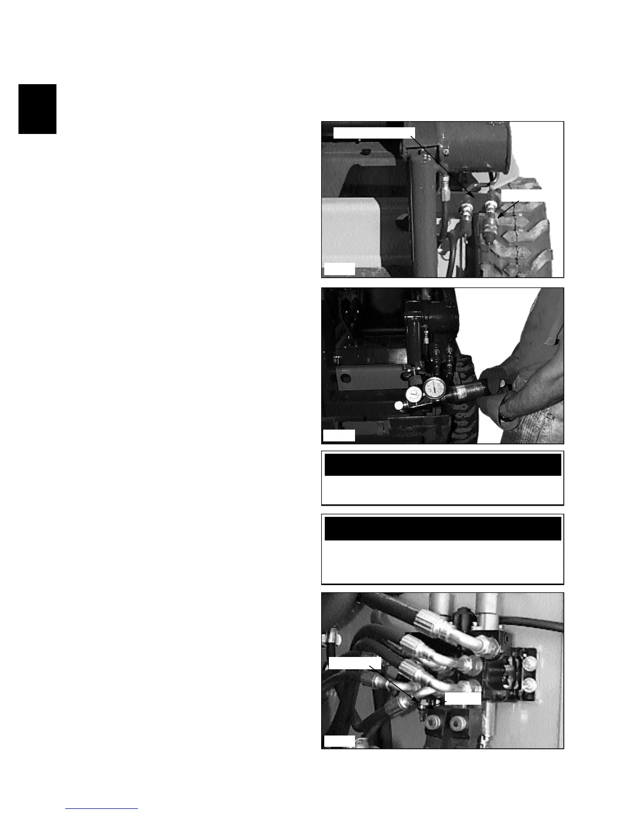
1 The female coupler attached to the loader provides
the power out when the auxiliary control is engaged. (fig.
C2351) Connect the flow meter and pressure gauge inlet
side to match the power out of the female auxiliary
coupler to prevent meter and gauge damage. Be sure to
connect a return line to the male auxiliary hydraulic quick
coupler. Install the flow meter / pressure tester to the
auxiliary hydraulic quick couplers. (fig. C2352)
2 Start the engine and engage the auxiliary hydraulic
system. Increase the engine speed to full operating RPM.
(See Section 7 for checking and adjusting engine speed to
3000 RPM plus or minus 25 RPM)
3 Turn the flow control valve on the flow meter to
restrict the oil flow down to 2 GPM. (7.5 LPM) As you
are turning the flow control valve, watch the pressure
gauge and make sure it does not go over 3000 PSI.(207
Bar) Stop further adjustment immediately if the reading
goes over this setting. Shut off the auxiliary hydraulic
system and shut off the engine. Move to step 6 to make
initial setting.
4 Repeat steps 2 and 3 if necessary. Allow the loader to
operate at this setting until the oil temperature has
increased to 160° F (71ºC), operating temperature.
5 Turn the flow control valve further to restrict the oil
flow to no flow. (Zero) Correct pressure setting is 2150
PSI +/- 100 PSI. (148 Bar, +/-6.9 Bar)
6 If adjustment is necessary, shut down the auxiliary
hydraulic system, shut off the engine and return the flow
control valve to the open position. Locate the control
valve in the engine compartment.
7 Loosen the jam nut on the relief valve adjusting
screw and turn the screw clockwise, counting the turns,
until the screw bottoms out. (fig. C2348)
8 Turn the screw back out lesser turns than you turned
in to increase pressure, or out more turns to decrease
pressure.
9 Retake the pressure readings by performing steps 2
through 5. If necessary make further adjustments by
repeating steps 6 through 9.
NOTE: If inadequate pressure and / or flow is not
available, the gear pump could be failing or the inlet
to the gear pump is restricted.
C2351
C2348
Relief valve
Jam nut
Pressure out
CAUTION
Adjusting the relief valve setting too high may cause
damage to the gear pump.
Auxiliary couplers
C2352
WARNING
To prevent personal injury or damage to the loader,
do not adjust the relief valve while the engine is
operating.