2-42
DRIVE MOTOR 2.12
C2320
C2321
C2322
C2324
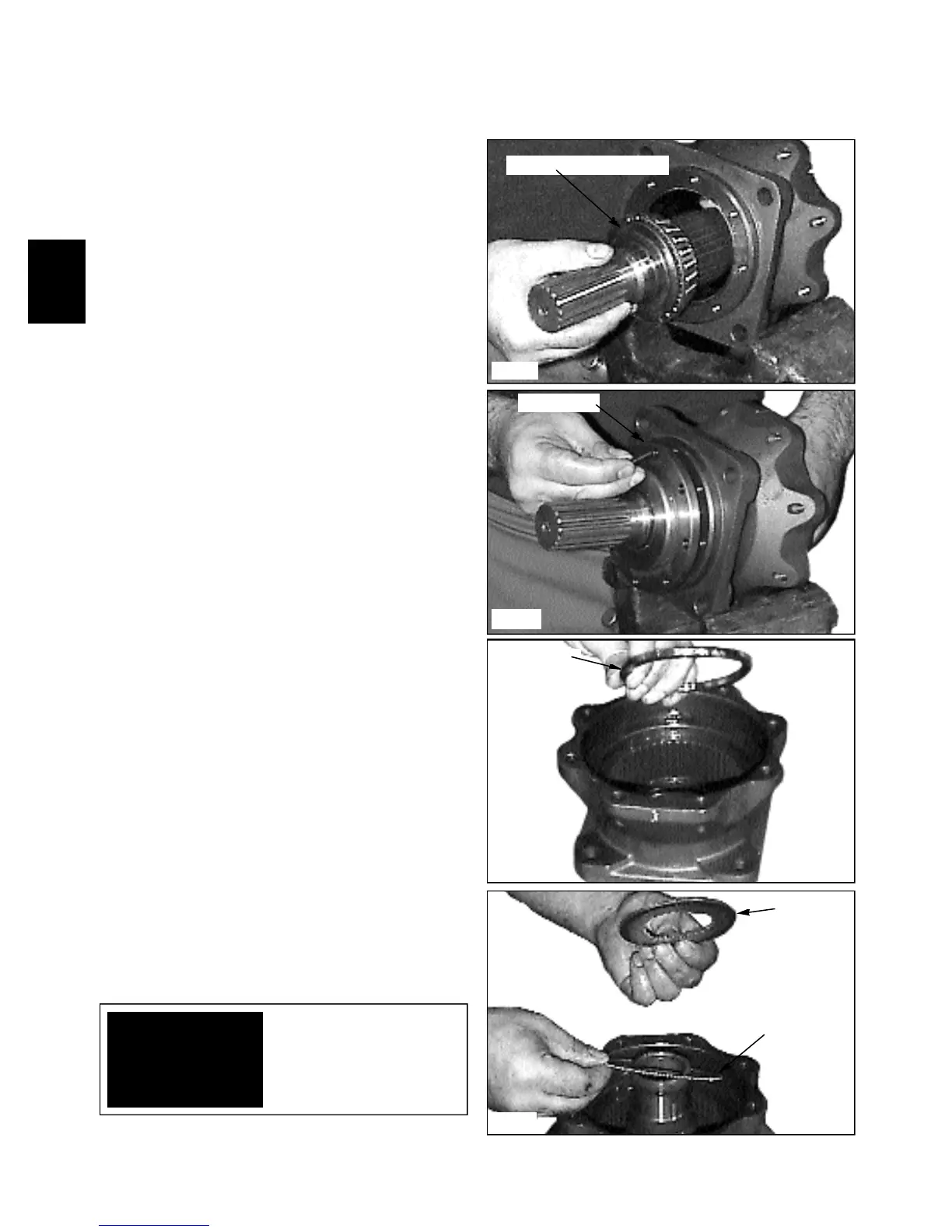
1 Install the output shaft to the housing. (fig. C2321)
Assembly
4 Install the brake disc plates. (fig. C2323, C2324,
C2319) Start with a fibre plate, add a steel plate, then
fibre and so on until the last plate to be installed is a fibre
plate.
3 Install the brake disc spacer ring to the housing. (fig.
C2320)
2 Install the front cover to the housing and torque the
screws to 12 Nm. (8.9 lbs / ft) (fig. C2322). Use new
seals when assembling the motor.
Front cover
Output shaft and bearing
Spacer ring
Add fibre plate first
Steel plate
IMPORTANT
NOTE:The fibre plates
are also called outer plates
due to the “teeth” outside
of the plate.