3-6
Chain Installation
DRIVE CHAIN 3.3
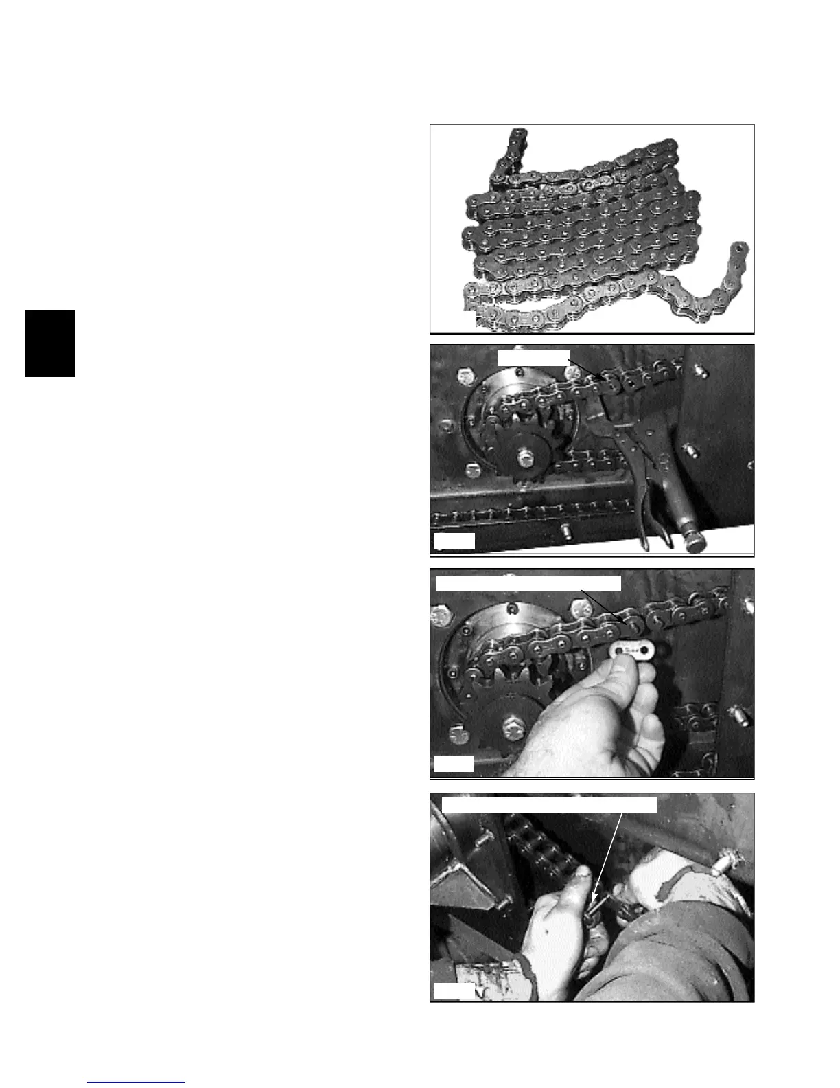
1 Wrap the chain in a “Z” pattern (fig. C2273).
2 Install the wrapped chain into the final drive housing.
C2427
C2428
Chain wrap
C2273
C2429
4 Wrap the chain around the drive motor sprocket and
install a new connecting link (fig. C2427).
5 Place the connecting link into the chain so the inside
chains connecting link has cotter pins face the inspection
cover hole (fig. C2428). The connecting link on the out-
side chain, closest to the inspection cover opening, faces
inward, (fig. C2429) toward the other chain. Bend the
ends of the cotter pins at least 90º apart.
6 Check the chain tension as outlined on Section 3.3.
7 Replace the inspection cover using silicone. Do not
over tighten the inspection cover nuts, 12 lbs / ft maxi-
mum. (16.5 nm). Be sure to clean sealing surfaces before
silicone application.
8 Replace the wheels and torque the wheel nuts to 100
to 110 lbs/ft. (136 to 149 nm).
3 Place one end of the chain over the top of the axle
sprocket. Rotate the axle by hand and bring the chain
along the bottom of the final drive housing to approxi-
mately the center.
Inside chain
Inside chain connector faces out
Outside chain connector faces inward