When installing a new control valve, always inspect the
exterior for shipping or other damage, such as bent
brackets, broken spring return caps or damaged spool
lock mechanism. Repair all damaged parts before
installation to the loader.
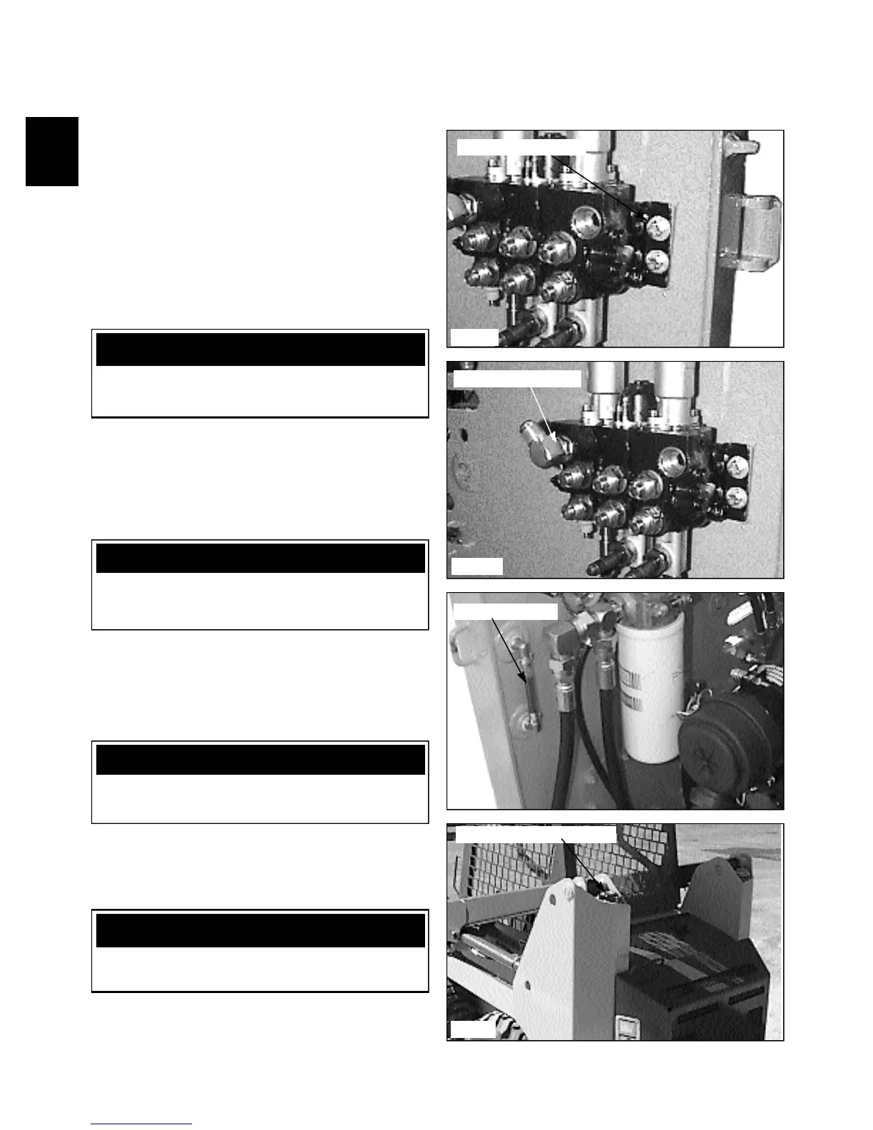
1 Mount the control valve to the loader. (fig. C2324a)
2 Connect the control cables to the spools.
3 Connect the various hydraulic lines to their proper
ports. (fig. C2324b).
4 Connect the solenoid coils to the control valve locks.
Apply a drop of Loctite 242 (blue) to the knurled
retaining nut.
5 Verify fluid level in th hydraulic oil reservoir. (fig.
C2354). Top off as required to bring oil level to
approximately half way in the site gauge.
1-10
CONTROL VALVE 1.3
C2324a
Control valve fittings
C2354
C2355
Check fluid level
Replenish fluid as required
Install valve to mount
C2423b
IMPORTANT
Follow the hydraulic fitting torque chart in Section
1.10 when connecting fittings and lines.
WARNING
Use extreme caution when checking the hydraulic
system for leaks. Fluid under pressure can penetrate
the skin and cause serious injury.
WARNING
All safety switches must be connected and
functioning to prevent possible operator injury.
Control Valve Installation
WARNING
Verify the relief valve pressure setting after replacing
or servicing the control valve.