1-9
CONTROL VALVE 1.3
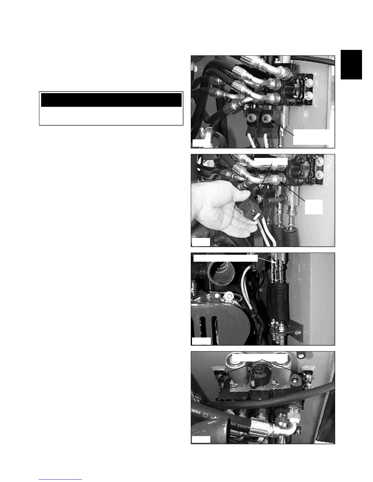
Control Valve Removal
1 Remove any attachment, lower the boom arms,
engage the parking brake and shut off the engine
2 Disconnect the spool locks solenoid, and electrical
auxiliary solenoid wiring connectors if equipped. (fig.
C2348, C2349)
3 Disconnect the control cables. (fig. C2367)
4 Disconnect the return line from the control valve and
remove the adapter fitting. Plug and cap all open ports
and hose ends.
5 Disconnect the 6 hoses going to the boom, bucket
and auxiliary circuits. Marking the hoses as you remove
them is recommended for safety and to ease re-assembly
and assure the circuits are functioning properly at restart.
6 Disconnect the the inlet hose coming from the gear
pump. Cap the hose and fitting and remove the adapter
fitting in the control valve.
C2349
Solenoid coil
Solenoid coil
mounting nuts
C2367
C2350
Return
line
C2348
IMPORTANT
Clean the work area prior to repair. Cap all open
lines, fittings and ports to prevent contamination.
Control valve mounts
Disconnect control cables
7 Remove the 4 bolts holding the control valve to the
mount and remove the control valve. (fig. C2350)