4-22
PARKING BRAKE 4.6
General Information
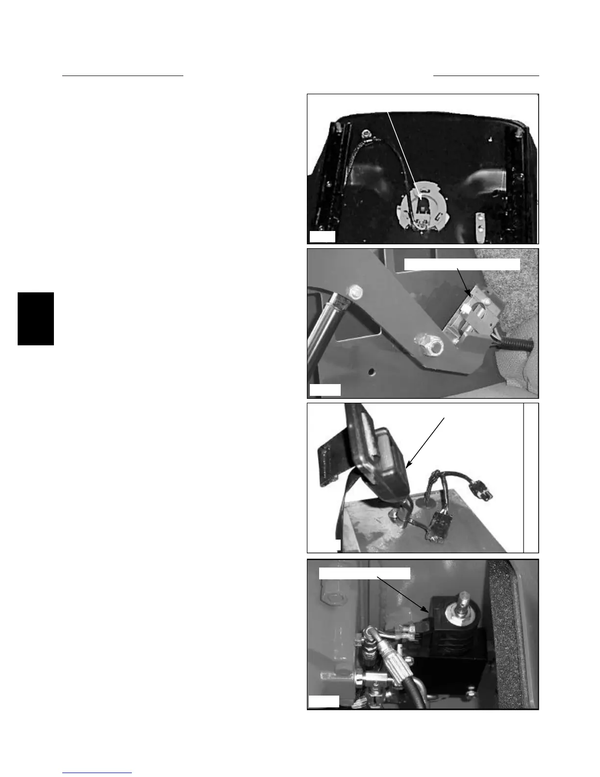
C807
Seat pressure switch
C3574
Seat belt safety switch
C3573
Restraint Bar Safety Switch
Solenoid Brake Valve
C3575
Each drive motor contains a set of clutch pack type fric-
tion discs that are spring loaded in the engaged position.
The parking brake is inter locked with various safety
switches. (fig. C807, C3573, C3574, C3575) The parking
brake will only release when the engine is operating, the
operator is seated with the seat belt fastened and the
restraint bar is in the lowered position.
The parking brake system requires 200 psi (13.78 bar)
hydraulic pressure to release or separate the clutch packs
in the drive motors. The hydraulic pressure is provided by
the charge pressure relief valve in the hydrostatic tandem
pump.
When the engine is operating and all safety switches are
functioning and in the closed position, the hydraulic /
electric solenoid brake valve (fig. C3575) will allow
charge pressure to release the parking brake in the drive
motors.