5-16
ELECTRICAL PANEL 5.7
The loader is equipped with a 12 volt, negative ground
electrical system. The fuse and relay panels are located in
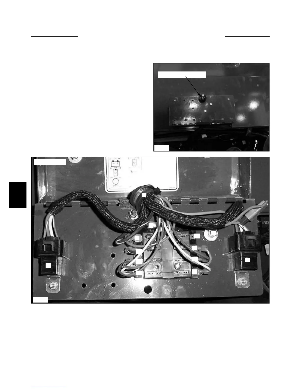
the engine compartment, attached to the underneath of the
engine cover. (fig. C3588)
To access the electrical panel:
1 Open the rear door and raise the engine cover.
2 Remove the bolt holding the electrical panel cover
closed. (fig. C3588)
3 Open the cover and all fuses and relays will be
exposed. (fig. C3589)
Visually check the fuses for burnt contacts.
The relays are identical and may be checked by swapping
one for the other to trace a malfunction. If changing the
relays around does not repair the problem, the problem is
somewhere else.
The ground bolt should be checked occasionally for cor-
rosion and cleaned if necessary. Use a dielectric grease to
protect the ground point from the elements.
C3588
Fuse panel access knob
C3589
7 Option (10Amp, YL / WH)
8 Manifold Heater Relay (40 Amp)
9 Option (10 Amp YL)
10 Auxiliary Solenoid (10 Amp, RED / YL)
11 Starter Relay (40 Amp)
12 Alternator (10Amp, BLK / WH)
13 Option (10Amp)
11
1
2
3
4
5
6
7
8
9
10
12
13
Electrical Panel
ELECTRICAL PANEL LEGEND.(fig. C2052)
1 Engine harness
2 Engine Shut Off (15 Amp, RED)
3 Power Inlet From Ignition Switch Acc (BLK / WH)
4 Grounding Point (LT GRN)
5 Safety Switches (15 Amp, OR / WH)
6 Horn / Option (10 Amp, BRN)