4-7
Tracking Adjustment (Speed)
Tracking adjustment, or wheel speed, is set individually
for L.H. and R.H. sides. If the operator complains the
loader does not go in a straight line when the levers are
pushed clear forward the limiter stops may need adjust-
ment.
1 Raise the boom arms, engage the boom support pins
and shut off the engine. Raise and block the loader
securely off the ground.
2 Remove the seat and hydrostatic shield. Note the
location of the steering control limiter bolts located front
and rear of each steering control lever, just below the
pivot point.. (fig. C3559)
3 Make sure the neutral adjustments are adjusted cor-
rectly. Refer to pages 4- 4 ~ 4-6.
4 If and when all rod bushings and pivot points have
been check for wear or binding, proceed with the wheel
speed adjustment.
5 Start the engine and release the parking brake. Adjust
the engine RPM to the full high idle position. Refer to
Section 7 to verify engine RPM.
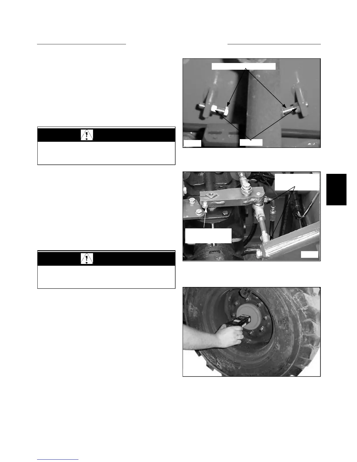
6 Using an RPM surface speed measuring tool
(Thomas P/N 43981) check each wheel speed in the for-
ward and reverse direction. Repeat for opposite side. (fig.
C3560)
7 Correct wheel speed is set evenly at 83 RPM forward
and reverse for both sides.
8 If adjustment is necessary, loosen the jam nut (fig.
C3559) and turn the limiter bolt in to increase wheel
speed or out to slow it down.
9 Tighten the jam nut and retest the speed adjustment.
Repeat if necessary.
10 Replace the seat and hydrostatic shield.
Note: If the wheel speed does not meet the above specifi-
cation, check the engine RPM. Refer to Section 7.
If the engine RPM checks out good you may need to
check for hydrostatic problems such as drive motor seal
leakage etc. Refer to Section 2 for testing procedures.
C3559
Speed control limiter bolts
Jam nuts
Check rod end
bushings for wear
Check pintle lever
tightness
C3560
STEERING 4.1
C3554
WARNING
Never work under the boom arms without the boom
supports engaged.
WARNING
Raise the loader securely off the ground before start-
ing the engine.