4-8
Control Lever Replacement
1 Raise the boom arms, engage the boom supports and
shut off the engine. Raise the loader securely off the
ground to prevent accidental engagement of the drive
functions upon restarting the engine.
2 Remove the seat and hydrostatic shield.
3 Remove the two bolts from the lever base.
4 Remove the control handle by turning counter clock-
wise.
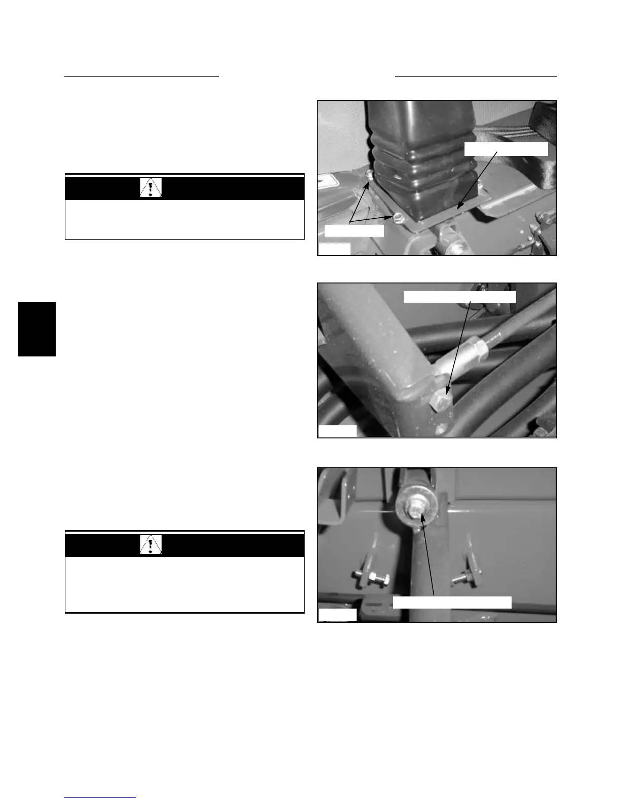
5 Remove the screws holding the bellows cover down.
(fig. C3561)
6 Remove the bolt going through the control rod and
hydro back linkage. (fig. C3562)
7 Remove the bolt and washers mounting the control
lever to it’s pivot point. (fig.C3559) The control lever is
now free to be removed.
8 Replace the control lever in the reverse order. Lightly
lubricate the pivot shaft with white grease when assem-
bling the control lever to the pivot shaft.
9 If necessary, make adjustments to the neutral center-
ing and wheel speed as required. Refer to pages 4 - 4 ~
4 - 7.
Note: If the loader is equipped with optional electrical
accessories operated by control handle mounted switches,
the control handle switch wiring will need to be discon-
nected and transferred to the new steering lever.
C3559
C3562
Disconnect control linkage
Remove the mounting bolt
C3561
Control lever cover
Remove bolts
STEERING 4.1
WARNING
Never work under the boom arms without the boom
supports engaged.
WARNING
Repairs or adjustment to the control lever system
may change the loader neutral position. Make sure
the loader is raised securely off the ground before
restarting the engine.