2-4
GENERAL INFORMATION 2.2
The driveshaft of the piston pump is rotated by the engine. The
piston block which is splined to the driveshaft also turns. The
piston block, rotating group, consists of 9 piston assemblies
which have free swiveling shoes swagged on the ball end of
each piston assembly. The shoe end of the piston rides against
the smooth machined surface of the swashplate. With the swash-
plate in the neutral position, the piston assemblies do not recip-
rocate in the piston block, but are rotating. No oil is drawn into
or discharged from the pump. The pump is in a zero displace-
ment position and the loader remains stationary.
With the swashplate in the neutral position, the pressure of the
charge oil, which ranges from 200 psi (13.8 Bar), is able to
unseat both check valves and supply oil to both sides of the
pump because of the balance in pressure. Very little charge oil
volume is required in the neutral position so the excess oil is
bypassed over the charge pressure relief valve and recirculated
back to the reservoir. The oil that leaks internally in the pump
and motor collects in their body housings and is returned to the
reservoir by external case drain in the pump and motors. This
leakage oil is the only oil the charge check replenishes. This
makes the design a closed loop system.
As the steering lever is moved forward, or reverse, the loader
starts a directional movement. As the swashplate begins to
move, the piston assemblies start to reciprocate in the piston
block. As the steering lever continues further movement the cam
angle increases, the pistons reciprocate further, more oil is
pumped and the speed of the loader is increased.
The drive motor, which is a fixed displacement type, delivers a
constant output torque for a given pressure throughout the speed
range of the motor.
The movement of the pump swashplate, forward or reverse,
controls the direction of the drive motor rotation.
The function of the pressure relief valve is to relieve the pres-
sure side of the system of excessive high pressure when the
loader encounters a heavy load or stalls out.
When the relief valve senses an over load it unseats, allowing
excess pressure and volume to flow into the low pressure side of
the pump. A small volume of oil starts to flow across to the
other relief valve. This relief valve is exposed to the low pres-
sure on the intake side of the pump and is seated by the spring
tension within the relief valve body.
The small volume of oil being bypassed is enough to unseat the
relief valve and let it recirculate back into the inlet side of the
pump. As the pressure continues to build on the pressure side, a
larger volume of oil flows and at a greater speed through the
drilled orifice in the relief valve cartridge, causing a pressure
drop inside the relief valve. The surrounding pressure is now
able to unseat the relief valve and bypass maximum volume of
oil. The system reliefs function the same for both sides of the
system.
When the swashplate begins to move the check valve on the dis-
charge, or pressure, side seats because of the higher pressure
differential. The other check valve remains open on the intake
or low pressure side to continue supplying the closed loop sys-
tem with charge oil.
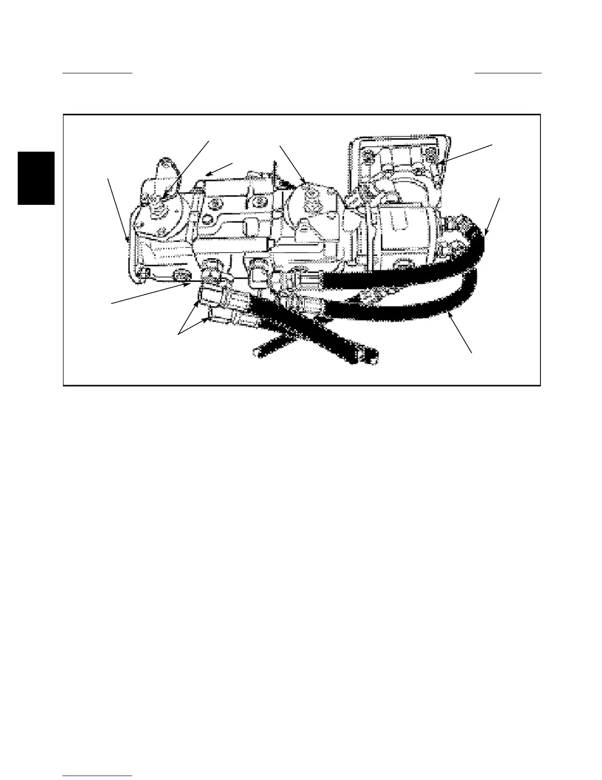
C3760
Clockwise input
shaft rotation
Counterclockwise
swash plate rotation
High pressure
High pressure
Case drain
High pressure
Fixed displacement
drive motor
Variable displacement
piston pump
Introduction:
Charge pressure inlet