2-9
PRESSURE TESTS 2.4
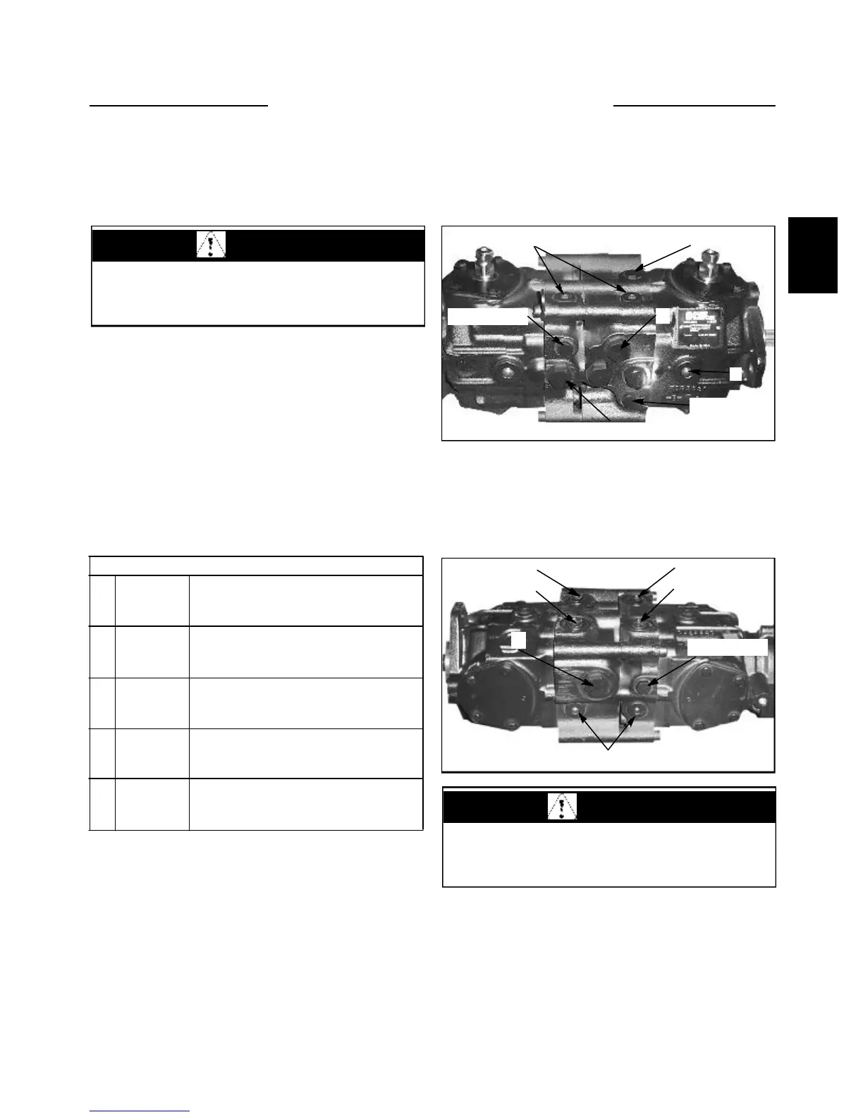
The following photos show the various port locations
available on the hydrostatic tandem pump for checking
system pressure.
Completing these pressure test will diagnose any mechan-
ical problem in the hydrostatic system.
Installing a gauge into the high pressure gauge ports ‘A’,
‘B’ , ‘C’, or ‘D’ will verify the status of the high pres-
sure relief valves.
Checking the pressure at port ‘E’ will give accurate
charge pressure reading.
Checking the pressure at port ‘F’ will verify case drain
pressure.
Measuring the vacuum at the charge pump inlet can help
locate the inlet lines and filters. It would be necessary to
tee into the charge pump line fitting.
Snubbers are recommended to protect the gauges from
pressure spikes. Frequent gauge calibration is necessary
to insure accuracy.
Gauge Information
A
B
C
D
G
System
Pressure
Gauge
System
Pressure
Gauge
Charge
Pressure
Gauge Port
Case
Drain
Port
Charge
Pump Inlet
Vacuum
10,000 PSI Gauge (690 Bar)
9/16 - 18 O-Ring Fitting
10,000 PSI Gauge (690 Bar)
9/16 - O-Ring Fitting
500 PSI Gauge (34.5 Bar)
7/8 - 14 O- Ring Fitting
500 PSI Gauge (34.5 Bar)
1 - 1/16 - 12 O-Ring Fitting
Vacuum Gauge (30 in. Hg)
Tee Into Charge Pump Inlet
Tandem pump flow can also measure pump performance.
1 Connect a flow meter between the high pressure
ports, one section at a time.
2 Start the engine and increase operating speed
between 1775 ~ 1800 RPM.
3 Restrict the flow to show 2000 PSI (137.8 Bar) over
charge inlet pressure.
Example: Charge pressure = 220 PSI (15.2 Bar) Gauge
pressure reading would need to be 2220 PSI (153 Bar).
4 Minimum flow reading should be 17.1 gal / min.
(64.7 L / min).
WARNING
Raise the machine securely from the ground before
performing system checks to prevent sudden move-
ment.
NOTE: Internal charge pump model shown
WARNING
Use caution when dealing with hydraulic fluid under
pressure. Escaping fluid under pressure can pene-
trate the skin and cause serious injury.
LH side and top view
F
G
Port B
Port A
Gauge port C
RH side and bottom view
High pressure relief valves A and C
High pressure relief valves D and B
Charge pressure relief valve
E
Gauge portD
Guage port B
Gauge port A
C4197
C4198
E
F
Port D
Port C