TOWING 2.5
Towing Procedure
In the event the loader has malfunctioned or failed, the
loader may be moved a short distance by following the
procedure below.
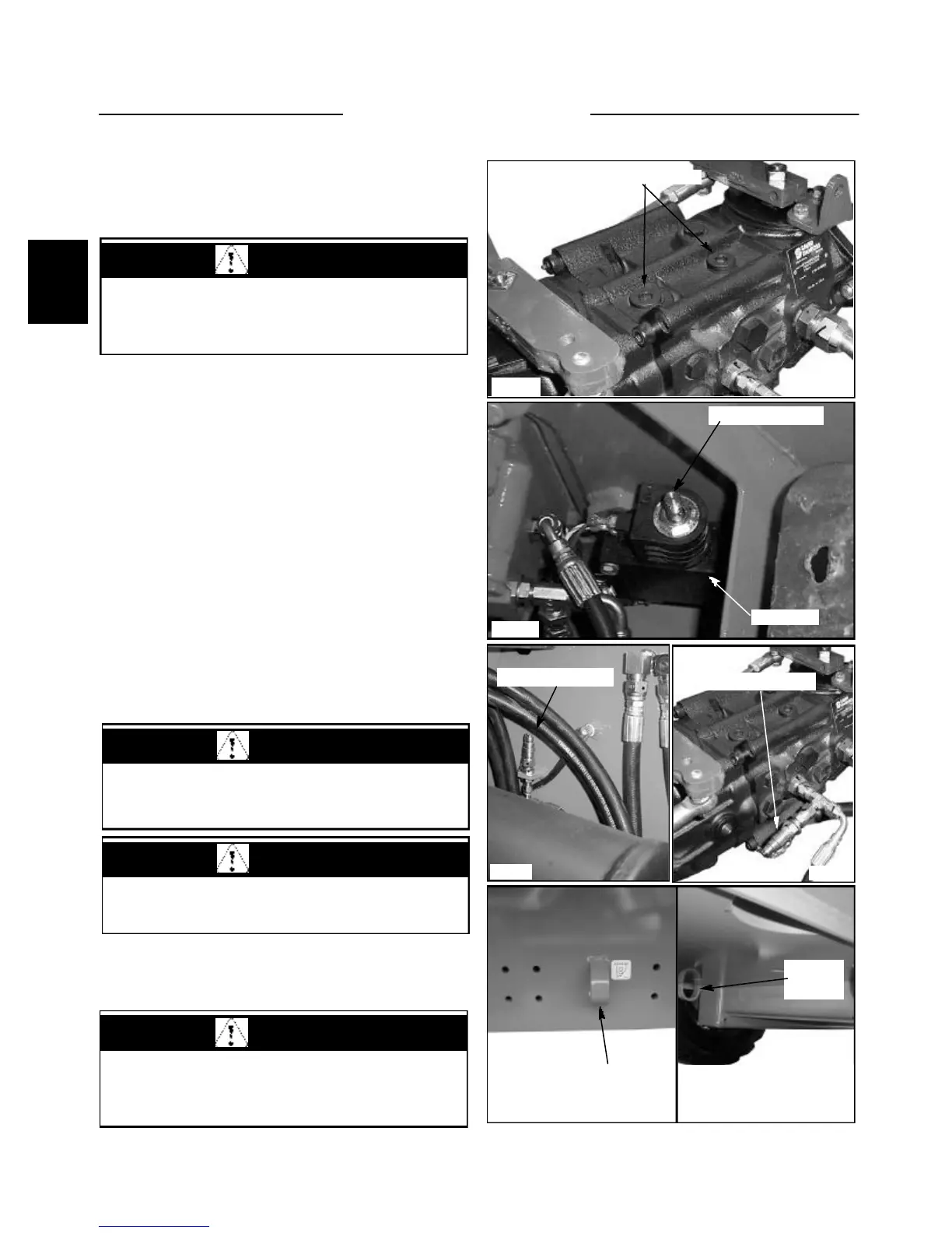
C3665
C3870
C3666
C3447
4 Use the front frame mounted tie downs to attach
pulling devise. ( fig. C3447 ) Use the rear tie downs to
pull the loader backwards. ( fig. C3446 )
1 Remove the seat and hydrostatic shield.
2 Loosen the high pressure relief valve caps 4 complete
turns. There are 4 high pressure relief valves, 2 on the top
side, and 2 on the bottom side of the tandem pump. Be
sure to loosen all 4. ( fig. C3665 ) Torque caps 30 to 50 ft
/ lbs (41 to 68 N.m.) upon reassembly.
3 The loader parking brake system is released by
hydrostatic pressure. To release the parking brake when
the unit has failed you must pressurize the brake system
manually. A service override for the brake valve has been
incorporated for use by Thomas Dealers. The normal
position of the plunger is down and turned into the locked
position. To release the brake, turn the release plunger
counter clockwise. (fig. C3666) Access of the small quick
connector for the 175 in the engine compartment.
(fiq.C3870) Access the small quick connector for the
1700 in the tandem compartment (fiq. C3871) Use a port
-a - power to pressurize this line to 200 psi (13.8 bar).
The brakes are now released.
C3446
Front tie down
Rear tie
down
Relief valve location
Brake release coupler
Brake release plunger
Brake valve
2-10
WARNING
Failure to follow the proper towing procedure may
cause damage to the hydrostatic drive system.
WARNING
Be sure to return the brake valve plunger to the
normal position after servicing the loader.
CAUTION
To prevent damage to the drive motors, do not
exceed speed of 1 MPH.
WARNING
Use chains or cables rated a minimum of 1 and 1/2
times the gross vehicle weight.
C3871
Brake release coupler