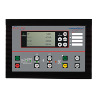
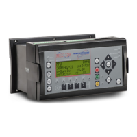
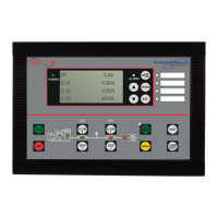
TSC 800 TRANSFER SWITCH CONTROLLER
PM 049 REV 9 06/04/24 Thomson Technology
7
2.5. OUTPUTS
The TSC 800 provides the following types of output circuits:
Engine Start Contact Isolated Form C contact (10A, 250VAC Resistive)
Programmable Output Contact Isolated Form C contact (10A, 250VAC Resistive)
Transfer to Utility Output 250VAC
1
, 10A (Resistive) powered output contact
Transfer to Generator output 250VAC
1
, 10A (Resistive) powered output contact
Pre/post-transfer to utility 250VAC
1
, 3A (Resistive) powered output contact
Pre/post-transfer to generator 250VAC
1
, 3A (Resistive) powered output contact
Load on utility 250VAC
1
, 3A (Resistive) powered output contact
Load on generator 250VAC
1
, 3A (Resistive) powered output contact
1
NOTE: Output voltage is dependent upon AC control power input voltage (i.e. 120VAC or 230VAC
nominal).
Interposing relays are required between the TSC 800 outputs and the end device if loads
exceed the output current rating.
Transient suppression devices are required for all inductive devices sharing wiring or if
physically located near the transfer switch controller.
For AC operated relays or solenoids, use a suitably rated metal oxide varistor (MOV) or
capacitor/resistor suppressor. MOV selection should typically be equal to or slightly greater
than 1.3 times the nominal RMS voltage being applied to the inductive device.
NOTE: Selecting an MOV of too low a value can/will result in a sustained short circuit and
ultimately result in equipment failure.
2.6. SYSTEM PHASING-HIGH LEG DELTA SYSTEMS
When the transfer switch is connected to 3 phase 4 wire delta systems and no multi tap
power supply transformers supplied with the ATS, the “High” leg, must be connected to
Phase B of the Utility and/or Generator supply inputs to the ATS (Phase B, colored Orange
per “NEC 384-3(e)” identified as the leg with highest potential with reference to ground). This
will ensure the ATS control power that is internally connected between phase A and neutral is
maintained at 120VAC. Refer to figure below for further details.
WARNING
Failure to match correct system phasing
will result in serious damage to the
TSC 800 controller.

 Loading...

