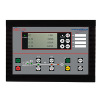
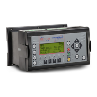
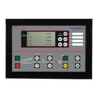
TSC 800 TRANSFER SWITCH CONTROLLER
PM 049 REV 9 06/04/24 Thomson Technology
63
127
600V
Displays the selected supply’s phase voltages to be calibrated.
Displays the type of calibration function, either ZERO or SPAN.
Displays the calibration correction factor number (0-255) used to obtain the
correct voltage reading. NOTE: To correctly calibrate any of the voltage
sensors, the ZERO function must be calibrated before the SPAN function. A
calibration correction factor number of 127 is typical of no correction offset
being applied, decreasing this value will apply a negative offset and
increasing this value will apply a positive offset.
Displays the actual voltage measurement, which will be the same value as
shown on the TSC 800 display menus for generator or utility supplies. This
voltage reading may be calibrated higher or lower by changing the correction
factor number and compared to a meter of known calibration to be within
0.5% or better and adjusted to match.
NOTE:
To accurately calibrate the TSC 800’s voltage
sensors, an external test voltage meter is
required, with an accuracy of 0.5% or better.
7.6.2. UTILITY VOLTAGE CALIBRATION
To adjust the utility supply voltage sensors, perform the following procedure:
7.6.2.1. ZERO CALIBRATION
7.6.2.1.1. Energize the generator supply to power up the controller and
de-energize the utility supply.
7.6.2.1.2. Scroll to the desired utility supply voltage phases with the
ZERO function selected. NOTE: The phases being calibrated for zero
must have a true zero reference to ground to allow proper calibration. A
zero voltage reference should be achieved as a result of a near 0 ohms
resistance through the source supply windings through to the neutral
star point connection which in turn is solidly bonded to the building
ground at one point in the system (where both the step down sensing
and power supply transformers are supplied with the transfer switch the

 Loading...

