TSC 800 TRANSFER SWITCH CONTROLLER
PM 049 REV 9 06/04/24 Thomson Technology
14
TB3
1
12
1
TB2
18
1
TB1
UTILIT Y SUPPLY
TRANSFORMER
GENERATOR SUPPLY
TRANSFORMER
4 3 2 1
CONTRAST
HD1
G;\ENGINEER\PRODUCTS\TSC800\852613b.VSD
10
9
8
7
6
5
4
3
2
1
1
2
3
4
HD2
WATCHDOG
ENGINE START
TRANSFER
TO UTILITY
TRANSFER
TO GENERATOR
COMM
RJ45
Connector
J7
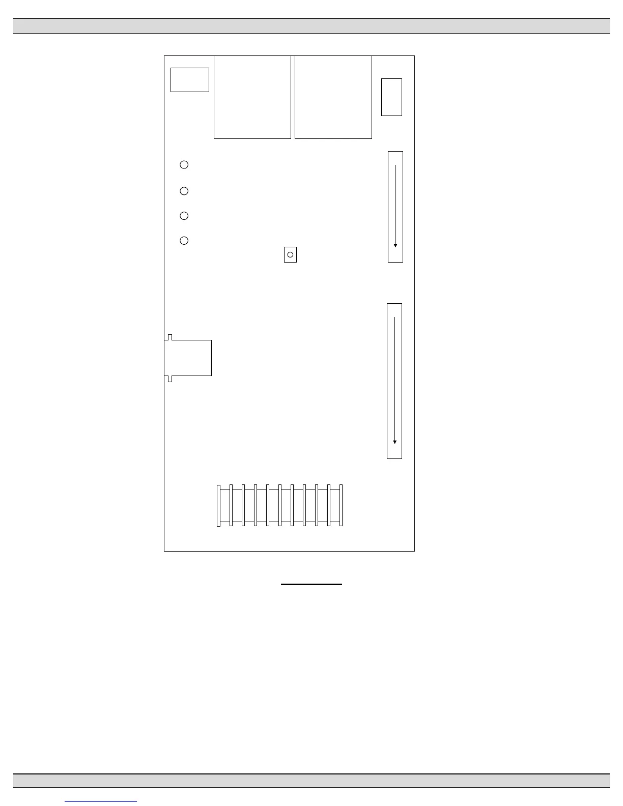
FIGURE # 8
3.2. PRINTED CIRCUIT BOARD
The printed circuit board (PCB) is shown in FIGURE 8. The PCB contains the following user
interface items:
3.2.1. POWER SUPPLY INPUT VOLTAGE SELECTION
The controller power supply input voltage level selection is made via two connector
plugs, which are located on the PCB and are identified as HD1 and HD2. Voltage
selection plug assemblies are unique for each power supply input level voltage
 Loading...


