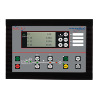
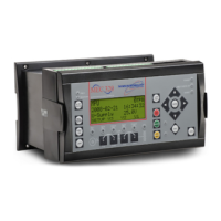
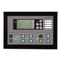
TSC 800 TRANSFER SWITCH CONTROLLER
PM 049 REV 9 06/04/24 Thomson Technology
50
The difference between the pickup and dropout setting is considered the dead band or
hysteresis value.
7.4.2. UTILITY UNDER VOLTAGE SENSOR DROPOUT
Set to the desired utility under voltage setpoint at which the internal voltage sensor
drops out (i.e. the sensor de-energizes to an abnormal state when any one of the utility
phase voltages is below the setpoint). The setting is entered based on a phase-to-
phase voltage value within a range of 70% to 99% of nominal system voltage. NOTE:
The difference between the pickup and dropout setting is considered the dead band or
hysteresis value.
7.4.3. UTILITY UNDER VOLTAGE SENSOR TIME DELAY (DROPOUT)
Select the desired utility under voltage time delay setting. The setting is entered in
seconds within a range of 0 to 10 seconds. If no delay is required, set this time delay
to zero.
Note: The utility Under Voltage time delay function is enabled if utility voltage drops
below the setpoint on one or more phases and the voltage remains between the
setpoint and 50% of nominal voltage. Should the utility voltage drop below 50% of
nominal value on all phases, the programmed time delay will automatically be reduced
to zero seconds. If a time delay feature is required under any condition, the utility
Under Voltage time delay should be set to zero and Generator Start Delay function
should be set to the desired time period.. Refer to section 7.5.2 for further details.
7.4.4. UTILITY OVER VOLTAGE SENSOR PICKUP
Set to the desired utility over voltage setpoint at which the internal voltage sensor picks
up (i.e. the sensor energizes to an abnormal state when any one phase of the utility
voltage is above the setpoint). The setting is entered based on a phase-to-phase
voltage value within a range of 101% to 200% of nominal system voltage. NOTE: The
difference between the pickup and dropout setting is considered the dead band or
hysteresis value.
7.4.5. UTILITY OVER VOLTAGE SENSOR DROPOUT
Set to the desired utility over voltage setpoint at which the internal voltage sensor
drops out (i.e. the sensor de-energizes to a normal state when all phases of the utility
voltage are below the setpoint). The setting is entered based on a phase-to-phase
voltage value within a range of 101% to 200% of nominal system voltage. NOTE: The
difference between the pickup and dropout setting is considered the dead band or
hysteresis value.

 Loading...

