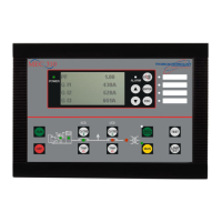
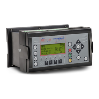
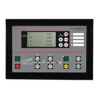
TSC 800 TRANSFER SWITCH CONTROLLER
PM 049 REV 9 06/04/24 Thomson Technology
15
arrangement and must match the intended voltage level. Controller failure may result
if incorrectly configured.
The TSC 800 is factory configured for a specific power supply voltage input as
designated by voltage header plugs labeled as follows:
115V - designates a 115V power supply input voltage
230V - designates a 230V power supply input voltage
3.2.2. TERMINAL BLOCKS
Three terminal blocks are located on the PCB as follows:
TB1 High voltage sensing terminal block (120-600VAC)
WARNING
Voltage sensing circuits are capable of lethal voltages while
energized. Standard safety procedures should be followed and
be performed by qualified personnel only. Failure to do so may
cause personnel injury and/or death.
TB2 Transfer control terminal block for output contacts and low voltage inputs
TB3 Transfer control terminal block for 115/230v input and output circuits
3.2.3. DIAGNOSTIC LEDs
The TSC 800 controller provides four diagnostic LED lights that are mounted on the
rear of the printed circuit board as per FIGURE 8. Their functions are described as
follows:
WATCHDOG This LED flashes on and off at irregular intervals that
indicate that the microprocessor is functioning
normally.
ENGINE START This LED is illuminated whenever the TSC 800 is
initiating an Engine Start (except when there is no
power to the TSC 800 controller).
TRANSFER TO UTILITY This LED is illuminated whenever the TSC 800 is
initiating a Transfer to Utility signal.
TRANSFER TO GEN This LED is illuminated whenever the TSC 800 is
initiating a Transfer to Generator signal.
NOTE: All LEDs will be illuminated whenever a lamp test function is performed.

 Loading...

