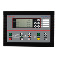
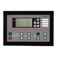
TSC 800 TRANSFER SWITCH CONTROLLER
PM 049 REV 10 08/09/25 Thomson Technology
78
Symptom Possible Causes
Will not transfer to generator
source upon failure of utility
source (cont’d)
Confirm voltage unbalance condition by viewing alarm state
on TSC 800 LCD. In this state the load is locked to the
utility source until the TSC 800 is reset
-
Transfer switch motor brake assembly will not release.
Possible interference with field installed wiring. Only
possible on 100 through 250 Amp ATS’s with exposed
mechanical brake.
-
Transfer to generator source
without a power failure in the utility
source
-
A test mode has been activated (check TSC 800 status LCD
display, can be via internal or external test inputs)
-
Defective TSC 800 controller (verify output signals with
circuit board mounted diagnostic LED’s)
-
Loose or broken wire to the utility voltage sensing terminals
on the TSC 800 controller
-
Failed voltage sensing circuit on TSC 800, repair or replace
controller.
-
Utility supply voltage is slightly above or below voltage
sensing set points. Compare TSC 800 program voltage set
points with actual utility voltage displayed on the controller
-
Incorrect voltage calibration providing incorrect readings for
Utility Sensing and being interpreted as being out of limit.
-
A transfer fail condition on the Utility PSD or limit switch has
occurred, review LCD for alarm condition, press lamp test to
reset.
-
A phase unbalance condition was detected on the Utility
supply while on load. The condition may not be readily
noticeable with no load on the source. Confirm voltage
unbalance condition by viewing alarm state on TSC 800
LCD. Press lamp test to reset.
*
Generator does not start up or stop
when it should
-
Verify remote engine control panel is set for automatic mode
and no shutdown faults present.
-
Verify remote engine start interconnect wiring properly
terminated (not open circuit).
-
Engine Start relay on TSC 800 has failed or been damaged
due to excessive current.
-
TSC 800 non-functional. Confirm the Watch Dog LED on
rear of circuit board to be flashing (processor healthy) and
the Engine Start LED is on confirming the start request.
*
No time delay when there should
be
-
Verify time delay function in the TSC 800 program setting as
per programming sheets as supplied with the transfer switch
-
Power is not available at the ATS
load terminals but the utility or
generator power switching device
appears to be closed to a live
source
-
The power switching device's trip unit (service entrance style
only) has tripped on a fault on the system and TSC 800
“Transfer Fail” is programmed as “Disabled or Halt
Transfer”. Correct the fault, and manually reset the power-
switching device in the transfer switch by moving it off and
then on again with the manual operating handle.
*
TSC 800 Display is Blank
-
Display in Sleep Mode. Press any keypad to re-energize the
display.
-
There is no power to the controller. Confirm power to the
controller from available supplies. Possible external
controller Power Transformer failed (PT1 & 2 )or controller

 Loading...


