LEVELING AND SLIDEOUT SYSTEMS
68
7
CUSTOMER CARE | 877.855.2867
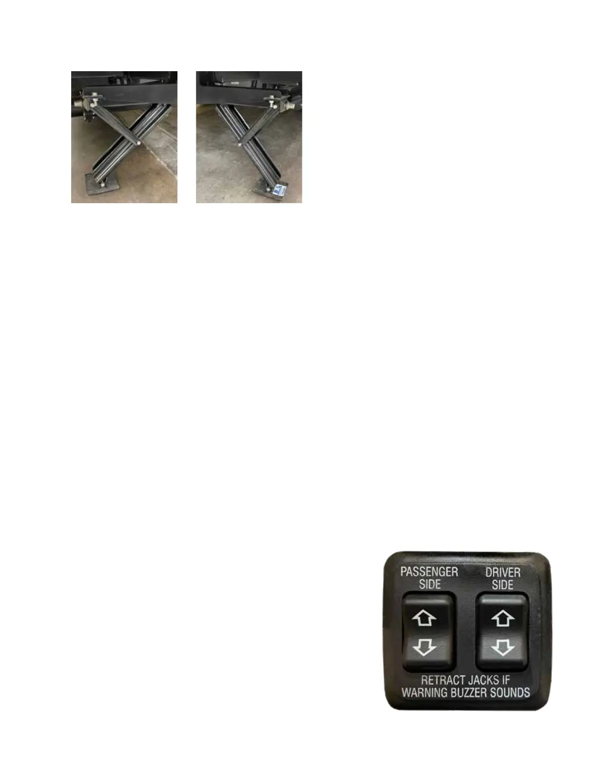
Typical
Electric
Stabilizer
Switch
Panel.
The panel
installed
in your
motorhome
may differ
from this
illustration.
Electric stabilizer jacks are oered on select TMC Class A
and Class C motorhomes and may be sourced from a variety
of manufacturers. If installed, the stabilizers are located
along the rearward portion of the chassis, just inside the
rear bumper. e operating controls are located inside the
motorhome, near the entry steps, or on some motorhomes,
integrated into the main multiplex control panel. Be sure
the electric stabilizers are fully retracted in the up (travel)
position before moving or driving the motorhome.
e following safety and operational instructions are gen-
eral in nature, yet apply to most electric stabilizing systems
installed by TMC.
NOTE: For optimum performance, the system requires
full battery current and voltage from the auxiliary (house)
battery(ies). This will make it possible for the motor to
fully extend and place the proper tension on the jacks. If
the auxiliary battery(ies) is/are weak, connect to shore
power or operate the generator while extending and
retracting the stabilizing jacks.
Prior to Operating the Electric Stabilizers
• Park the motorhome on a reasonably at and rm area.
Care must be taken when selecting a parking area since
the system is designed to provide stabilization, rather
than leveling. Always be mindful that the motorhome
must be level and stable prior to extending and retract-
ing slideouts.
e parking surface must be rm enough to prevent the
stabilizer's support pad from sinking into the ground.
Use of Jack Pads (16 to 24-inch plywood squares or
circles placed underneath the support pads) may be
required when parked on so surfaces.
• Place the vehicle's transmission in PARK and ENGAGE
the parking brake.
• Turn OFF the vehicle's ignition. Most stabilizer systems
have safety warning buzzers to signal that the vehicle's
ignition is ON while attempting to operate the stabilizers.
• If towing a trailer or vehicle, disconnect it from the
motorhome's hitch and chock trailer or towed vehicle's
wheels.
• Prior to ANY system operation, visually conrm that
the area above and below the stabilizer support pads is
clear of people, pets, objects, or obstructions.
• Always DEPLOY the stabilizers BEFORE extending
slideouts.
• Always RETRACT slideouts BEFORE retracting
stabilizers.
To Extend:
1. Turn ON the master battery switch. Doing so provides
power to the electric stabilizer system.
2. PUSH and HOLD the EXTEND switch, passenger
side or driver side (down arrow). e corresponding
stabilizer jack will deploy as long as the switch is held,
or the stabilizer reaches its fully deployed limit. Operate
the jack until the support pad contacts the ground, with
a slight liing of the motorhome, but NOT to where the
wheels are lied o the ground.
3. Once the stabilizer's support pad rmly contacts the
ground, release the EXTEND switch.
4. Repeat with the opposite side EXTEND switch.
5. To interrupt the jack travel, such as stopping deployment
to adjust jack pads, simply release the EXTEND switch.
Continue deployment by pushing and holding the switch
in the desired direction.
Typical left and right-side electric stabilizer jacks. For most systems, the
left and right-side jacks operate independently.
 Loading...