LEVELING AND SLIDEOUT SYSTEMS
69
7
THOR MOTOR COACH | MADE TO FIT
To Retract:
1. Ensure the master battery switch is ON.
2. PUSH and HOLD the RETRACT switch (up arrow)
until the stabilizer is fully retracted to the stowed posi-
tion. Release the switch when the stabilizer motor stops.
3. Repeat with the opposite side RETRACT switch.
4. To interrupt the jack travel, such as to brush o mud
or dirt from the support pad, simply release the switch.
e stabilizer motor will stop.
To continue with the RETRACT cycle, PRESS and
HOLD the RETRACT switch until the stabilizer jack
is in its fully stowed position.
NOTE: Do not attempt to move the motorhome until the
stabilizers are fully retracted in their stowed position.
Damage to the stabilizers, motorhome's chassis, or
other components could occur.
Manual Override Procedure
• Always disconnect the jack motor from the electrical
system prior to manually operating the system.
Failure to do so can cause electricity to back-feed
through the motor and cause severe damage to the
system as well as void the manufacturer’s limited
warranty.
• Keep hands clear of the mechanism and use caution
as the coach chassis may lower as the stabilizers
are retracted.
• Do not use this procedure to over-extend the
stabilizers.
• Do not use this procedure as a means of using the
stabilizers as a jack to lift the motorhome's wheels
off the ground.
• When manually extending or retracting the jacks, be
sure not to overly force the actuator screw.
• The gears can be stripped out of the stabilizer jack if
the operator continues to rotate drive coupler beyond
the jack's full extension or retraction.
CAUTION
If an electrical problem with the stabilizing system occurs,
a manual override can be performed to extend or retract
the stabilizers.
1. If possible, disconnect the electrical connector(s) from
the drive motor(s). Doing so will prevent induced
voltages from damaging control circuitry.
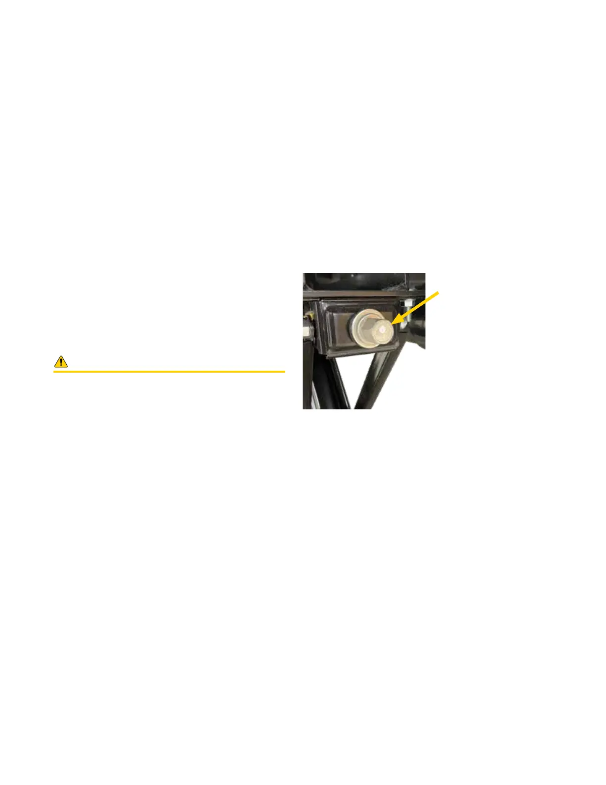
2. Locate the override coupler on the end of the drive screw
housing (see illustration below).
3. Place a 3/4" wrench or socket on the override coupler
and turn:
a. Clockwise to RETRACT.
b. Counter-clockwise to EXTEND.
NOTE: Some electric stabilizer systems require dis-
connecting the electrical connector to the drive motors
before manually extending or retracting the stabilizer
jacks.
NOTE: Electric stabilizers may be installed on motor-
homes with a Multiplex Control System. In such applica-
tions, the control switching for the electric stabilizers is
usually located on the MOTORS Control Screen, along
with Slideouts and Awnings. It may be necessary to scroll
down the screen to locate the control buttons for the
electric stabilizers.
NOTE: Complete instructions regarding the operation
and maintenance of the electric stabilizer system installed
on your motorhome are available through your on-line
TMC Owners Resource account.
This illustration shows the location of the electric stabilizer drive coupler.
Each side, left and right, has a drive coupler.
Turn 3/4" drive coupler to
manually extend or retract
the stabilizer.
NOTE: Size of the drive
coupler nut may vary due
to manufacturers design
preference.