Page 17
PM5020 Dual-Channel Benchtop Power and Energy Meter Chapter 4 Operating Instructions
Rev: 1.0, 18-Aug-2022 © 2022 Thorlabs
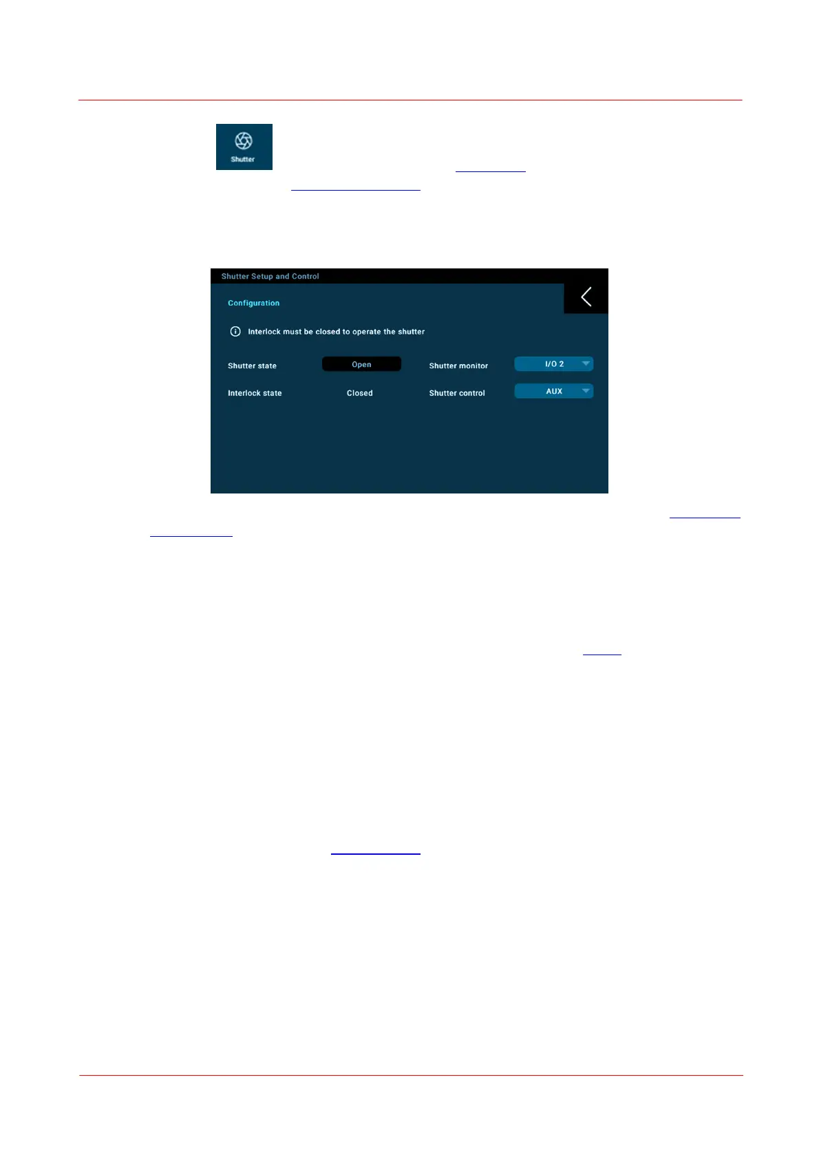
Shutter Settings
A shutter control icon automatically appears in the side menus of any measurement screen when
a SH05R(/M) or SH1(/M) Thorlabs optical beam shutter is connected to the Hirose HR10A-7R-6S connector.
Operating the shutter requires an interlock to be connected to the 2.5 mm mono audio interlock con-
nector in the rear panel. The position state of the shutter is monitored and displayed on the touch screen.
The settings menu provides the following interface:
The shutter, in addition to manual control in the GUI, can be monitored and controlled by the Digital I/O2
or the front AUX I/O BNC connector using a TTL signal.
4.10 Fan Control
The PM5020 power meter allows the connection and control of two up to 12 VDC fans with adjustable sup-
ply voltage or by adjustable number of revolutions per minute (rpm) for 3-wire fans with tacho input.
This feature reserves an extra power supply for fan-cooled sensors, such as the S322C, or can be used to
run other cooling fans in the optical setup.
The fans can be operated by:
• Setting of the DC voltage up to 12 V.
• Setting a fan speed, depending on the temperature detected by either the built-in sensor temperature
sensor or a connected external NTC. Set a start temperature and a maximum temperature where the fan
runs at full speed. The speed will increase with rising temperature.
• Setting of the rpm when the fan provides a tacho signal. In this case please set the maximum rpm and
the desired rpm.
Open the Fan Setup Control menu in the Settings Menu to adjust the fan control settings.
 Loading...


