EasyManuals Logo

THORLABS PM5020 User Manual

THORLABS PM5020
65 pages
To Next Page IconTo Next Page
To Previous Page IconTo Previous Page
Page #59 background imageLoading...
Page #59 background image
Page 55
PM5020 Dual-Channel Benchtop Power and Energy Meter Chapter 5 Specifications
Rev: 1.0, 18-Aug-2022 © 2022 Thorlabs
Pin
Function
Description
1
I/O 0
Input/Output Port or alternative function pass/fail or disable analog port to be set
in the settings menu
2
I/O 1
Input/Output Port or alternative function pass/fail or disable analog port to be set
in the settings menu
3
I/O 2
Input/Output Port or alternative function shutter control or shutter monitor
4
I/O 3
Input/Output Port or alternative function logging control or logging monitor
5
TRIG
Trigger Input/Output
6
GND
Ground
7
SCL
I2C Bus Clock
8
SDA
I2C Bus Data
9
3V3
Power Supply for Accessories, 3.3 V, 100 mA Max
10
5 V
Power Supply for Accessories, 5 V, 100 mA Max
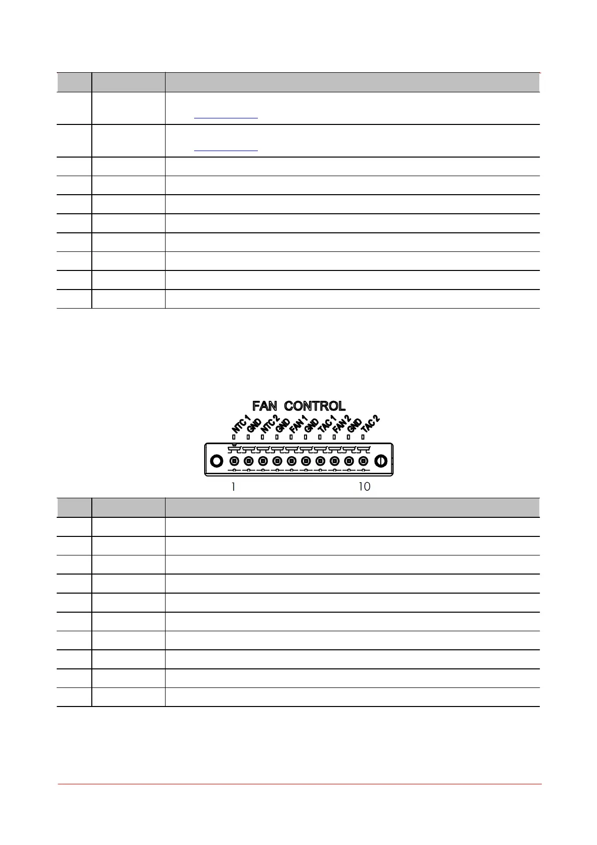
5.4 Pin Fan Control
The PM5020 has a Fan Control Connector. The Pins are assigned as follows:
Pin
Function
Description
1
NTC1
Input External NTC1
2
GND
Ground NTC1
3
NTC2
Input External NTC2
4
GND
Ground NTC2
5
Fan1
Supply Fan1
6
GND
Ground Fan1
7
TAC1
Optional Tacho Signal of Fan1
8
Fan2
Supply Fan2
9
GND
Ground Fan2
10
TAC2
Optional Tacho Signal of Fan2

Questions and Answers:

Question and Answer IconNeed help?

Do you have a question about the THORLABS PM5020 and is the answer not in the manual?

THORLABS PM5020 Specifications

General IconGeneral
BrandTHORLABS
ModelPM5020
CategoryMeasuring Instruments
LanguageEnglish

Related product manuals