Page 53
PM5020 Dual-Channel Benchtop Power and Energy Meter Chapter 5 Specifications
Rev: 1.0, 18-Aug-2022 © 2022 Thorlabs
Graphical IPS LCD w. Touch 854 x 480 Pixels
5.0" (4.32" x 2.43", 109.7 x 61.6 mm)
Numerical, Bargraph, Needle,
Graph Power/Position/Temperature, Statistics
Operating Temperature Range
1
)
Storage Temperature Range
Max. 80% up to 31 °C, Decreasing to 50% at 40 °C
Pollution Degree (Indoor Use Only)
253.2 mm x 110.6 mm x 293.6 mm
(9.97" x 4.35" x 11.56")
1
) non-condensing
2
) Weight of the PM5020 power meter, excluding all shipped accessories.
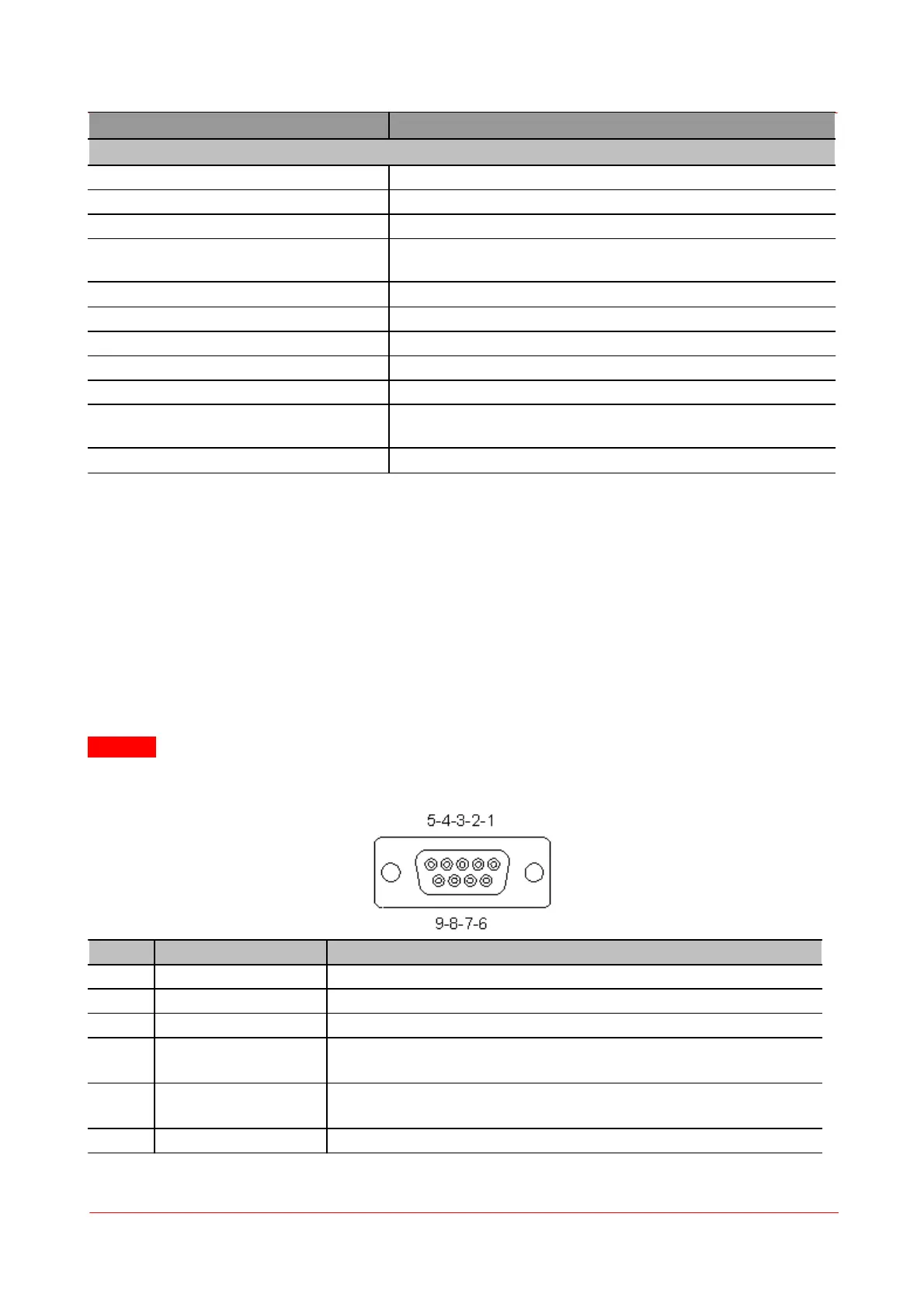
5.1 Pin Sensor Connectors
The sensor connector allows the access of all Thorlabs “C-type" photodiode, thermal, and pyroelectric
sensors. The power meter interface uses the sensor calibration data, stored in the sensor connector, to cal-
culate the corresponding actual power levels.
Additionally, the PM5020 is capable to support custom made detectors. Please read the following instruc-
tion prior to connecting a self made sensor.
Warning
Pin 2 is uniquely used for the EEPROM Digital I/O (memory in Thorlabs sensor heads) and MUST NOT be
used. Connecting this Pin may cause malfunction of the PM5020.
+5 V; Max Current 50 mA from this Pin
Sensor Memory for the Calibration Data
Analog Ground for Photodiode, Thermal, Pyroelectric Sensor, NTC
Photodiode Cathode Input /
Thermal Position Sensor Input Quadrant 3
Pyroelectric Sensor Input /
Thermal Position Sensor Input Quadrant 4
Digital Ground for EEPROM and 5V Output