Page 15
PM5020 Dual-Channel Benchtop Power and Energy Meter Chapter 4 Operating Instructions
Rev: 1.0, 18-Aug-2022 © 2022 Thorlabs
Once this is set, a "T" with white background will appear in the top panel. This white background will turn
yellow whenever acquisition is triggered.
This internal trigger can be used in all measurement screens except the Logging screen.
4.7.2 External Trigger
Measurements can be triggered externally via the auxiliary BNC port on the PM5020 power meter front
side or the Digital I/O connector in the read side.
For both, front BNC I/O and rear Digital I/O, set an external Low Voltage TTL (LVTTL) or TTL signal to high to
trigger acquisition and to low to stop it. The external signal triggers the start of a measurement on the
rising edge of an external LVTTL or TTL signal.
Configure the connector using the PM5020 touch screen Digital I/O and Control in the Settings Menu.
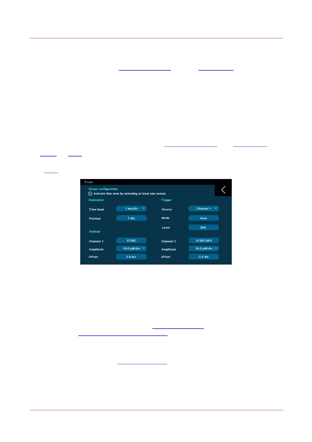
The logging and scope measurement screens can be used to acquire signal upon an external trigger.
After connecting the trigger sources via either the Digital I/O or the BNC I/O, go to the Settings Menu, sub-
panel Scope and configure the external trigger:
Here, also a signal from another channel can be used to trigger acquisition.
Trigger Signal Output:
Whenever a trigger is manually executed on the PM5020, a high TTL signal is sent to the I/O port.
4.8 Environment Setup
In addition to monitoring the temperature of the light sensors from their built in NTCs, two external NTC
temperature probes can be connected either at the 2.5 mm audio sockets (compatible to the Thorlabs TSP-
TH probes) or at the 10-PIN PCB Connector for Fan Control.
The temperature read from the connected light sensors, from the NTCs on the audio sockets, and the FAN
I/O is displayed in the top row of the measurement screen.
NTC configuration