The EI Inverter – Communications Connections
EI Residential Solar Solution US Installation Manual | www.tigoenergy.com | Help Center 12
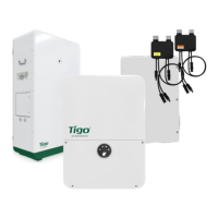
To connect to the ATS, first determine if your inverter has a two-pin
COM
power terminal
socket. This image shows an occupied socket:
If absent, disregard 12V DC cable instructions and only connect the two-wire RS-485 cable.
1. Prepare:
• A two-wire 18–20 AWG 12V DC cable
• A two-wire RS-485 cable
2. Locate the 2-pin, 3-pin, and 6-pin plugs included in the EI Inverter and EI ATS box
Accessories
bags. The 2-pin plug is not included with models lacking a 2-pin socket.
3. At the inverter, connect the 12V DC cable to the
+
and
–
terminals on the 2-pin plug
and install the plug.
4. At the inverter, connect the RS-485 cable to the
A
and
B
terminals on the 3-pin plug
and install the plug
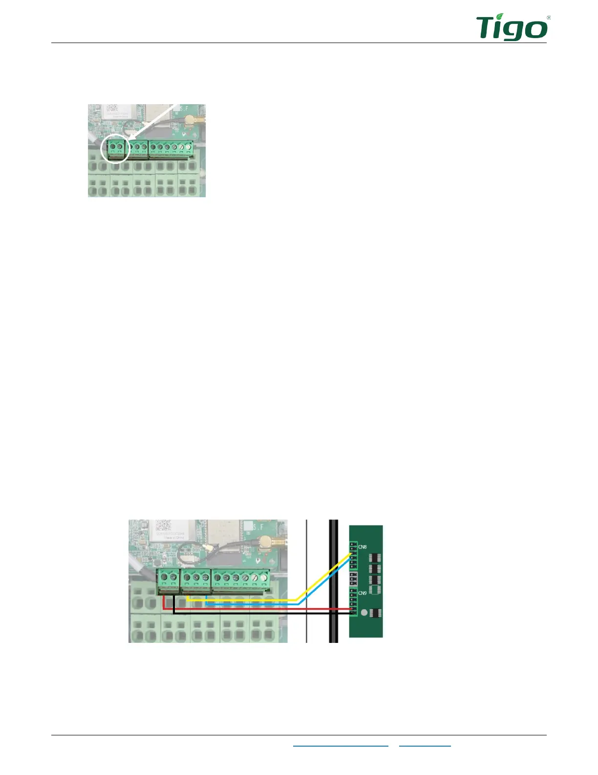
5. At the ATS, connect the 12V DC cable to the
+12
and
GND
terminals on the 6-pin
CN8
plug and install the plug.
6. At the ATS, connect the RS-485 cable from the A terminal of the inverter 3-pin plug to
the A terminal on the 6-pin
CN9
plug.
7. At the ATS, connect the RS-485 cable from the B terminal of the inverter 3-pin plug to
the B terminal on the 6-pin
CN9
plug.
8. Install the plug.