11-6
Twist Owner’s Manual
OM_TWIST_0811RevA
CHAPTER 11: CASTERS AND FORKS
Relacing the Elastomer Shock
Tools Needed:
• Two 5/32” Allen Wrench
1. Remove the Allen screws from the hinge and push out the threaded spacer. See Figure 11-9.
2. Separate the two halves of the Frog Legs
®
to release the elastomer shock.
Note: The metal disc is glued to the top of the elastomer shock.
3. Install the new elastomer shock (making sure the metal disk is facing upward).
4. Push rmly on the two halves of the Frog Legs
®
to facilitate reinstalling the Allen screws and threaded spacer.
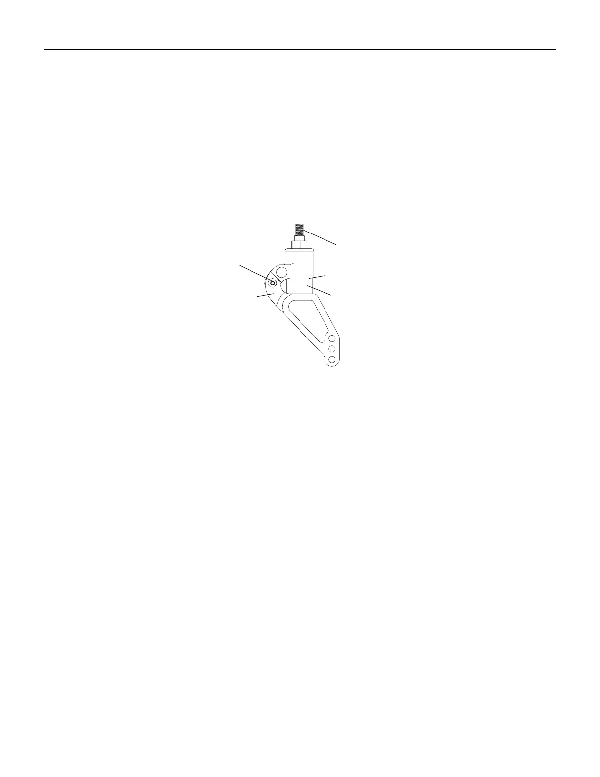
Figure 11-9
Replacing the Elastomer Shock on Frog Legs
®
Allen Screw and
Threaded Spacer
Elastomer
Shock
Fork Stem
Metal Disk
Hinge
IWARNING
The threads on the Allen screw that connects the two halves of the Frog Legs
®
are treated with Loctite
®
242
®
, a
medium strength thread lock. If you loosen this Allen screw, you MUST remove and reapply Loctite
®
242
®
or an
equivalent medium strength thread lock.
If you ignore this Warning, your rear wheel could become loose or fall off
and you could fall, tip over or lose control of the wheelchair and seriously injure yourself or others or damage the
wheelchair.
Replacing Frog Legs
®
Tools Needed:
• 1/8” Allen Wrench
• 3/16” Allen Wrench
1. Remove the casters. See “Frog Legs
®
– Replacing Casters” on pages 11-5 to 11-6.
2. Using the 1/8” Allen wrench, remove Allen screw 1 (outer screw) and the washer. See Figure 11-10.
3. Using the 3/16” Allen wrench, remove Allen screw 2 (center screw) and the washer. Holding the caster end cap
and caster mount in place, slide the old Frog Legs
®
fork and caster cap out and slide the replacement Frog Legs
®
fork through the caster housing and into the caster mount.
4. Using a Bubble Level Bracket, you must square the barrel of the Frog Legs
®
to the level surface because the at
edge of the Frog Legs
®
fork is not parallel to the caster mount assembly. See Figure 11-15.
5. Using the 1/8” Allen wrench, place Allen screw 1 through the washer, end cap and into the caster mount. Do not
tighten. While holding the fork in place, and with the end cap tabs engaged in the tab slots, check to see if one
of the six perimeter holes in the caster end cap aligns with one of the three threaded holes in the caster mount. If
so, proceed to Step 7. If not, proceed to Step 6.
6. Pull the caster end cap away from the caster housing and rotate the caster end cap one-sixth turn and re-engage
the caster end cap tabs in the tab slots. Again, check to see if one of the six perimeter holes in the caster end cap
aligns with one of the three threaded holes in the caster mount. If so, proceed to Step 7. If not, repeat this Step 6
using the next combination of caster end cap tabs and tab slots.
7. Thread Allen screw 1 through the two aligned parts and loosely tighten.
Note: There are six perimeter holes in the caster end cap and three threaded holes in the caster mount. These
are designed to permit 17° of adjustment in 1° increments.