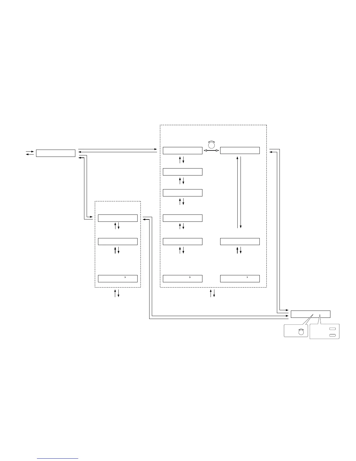
Paging input channel setting
(p. 65-D1)
PA
G
IN
GO
N IN1
Trigger setting
(When Trigger is set to "C-IN")
(p. 65-D2)
Control input terminal setting (p. 66-D5)
Paging zone and
Output channel settings
(p. 65-D4)
PA
G
IN
G
Z
O
NE1 C- IN01
PA
G
IN
G
Z
O
NE1
O
UT1
Interlock output control setting (p. 66-D6)
PA
G
IN
G
SYNC
O
FF
SYNC
O
UT C-
O
UT
01
(When Interlock output control is set to ON)
Interlock output terminal setting (p. 66-D7)
Paging prohibited channel and
control input terminal settings
(p. 67-D9)
PA
G
IN
G
DISABLE
O
FF
Paging prohibition setting
(p. 66-D8)
(Only when Paging prohibition is
set to ON)
Paging prohibited channel and
control input terminal settings
(p. 67-D9)
PA
G
IN
G
DISABLE
O
FF
Paging prohibition setting
(p. 66-D8)
(Only when Paging prohibition is
set to ON)
Paging prohibited channel and
control input terminal setting
(p. 67-D9)
PA
G
IN
G
DISABLE
O
FF
Paging prohibition setting
(p. 66-D8)
(Only when Paging prohibition is
set to ON)
Trigger setting
(When Trigger is set to "VOX")
(p. 65-D2)
PA
G
IN
G
TRI
G
V
O
X
Trigger setting
(When Trigger is set to "ZP")
(p. 65-D3)
PA
G
IN
G
TRI
G
ZP
Trigger settingTrigger setting
(For the channel on which the module other than the ZP-001T is used)
(For the channel on which the D-001T
is used)
(For the channel on which the ZP-001T is used)
DISABLE
O
UT1 CIN01DISABLE
O
UT1 CIN01 DISABLE
O
UT1 CIN01
P. 55
PA
G
IN
G
TRI
G
C- IN
PARAMETER
To select,
OUTPUT SEL
To determine,
ON/OFF
PARAMETER
To select,