82
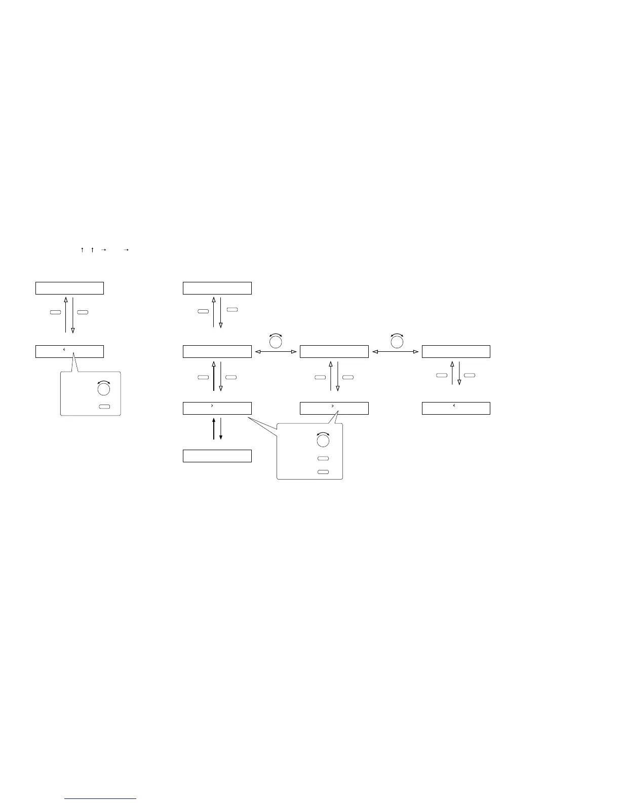
10.10.1. Setting flow chart
The screen display examples shown below may differ from actual displays.
The on-screen indications shown in red here (actually shown by flashing cursors) are parameters or setting contents
to be selected with the Parameter setting knob, input channel selection key or other designated keys.
The indications of the [ ], [ ], [ ], and [ ] arrows represent that the screen is switched with the Screen shift key.
Unless otherwise specified, use the Parameter setting knob for each parameter selection.
10.10. Memory Setting
L
O
AD 01
Scene memory setting
(when SAVE is set) (p. 83-H2)Scene memory recall
(p. 83-H1)
–––
Normal use state
–––
Normal use state
SCENESETT I N
G
SAVE
Scene memory setting
(when ERASE is set)
(p. 83-H2)
SCENESETT I N
G
E RA S E
Scene memory name setting (p. 84-H4)
BANK0 1NA
M
E=_______
ENTERESC/BACK ENTERESC/BACK
ENTERESC/BACK
PARAMETER PARAMETER
Scene memory setting
(when P-ON is set)
(p. 83-H2)
SCENESETT I N
G
P –
O
N
Scene memory save (p. 83-H3) Scene memory erasure (p. 84-H5)
Scene memory bank number to
be recalled at power-on (p. 84-H6)
P
O
W
ER
O
N LASTSTATESAVE 01 ERASE 0
1
MEMORY
MEMORY
MEMORY MEMORY
Press for over 2 seconds.
To select,
To determine,
ENTER
PARAMETER
PARAMETER
ESC/BACK
To select,
To determine,
To cancel,
ENTER