2-13
Chapter 2
NOMENCLATURE AND FUNCTIONS
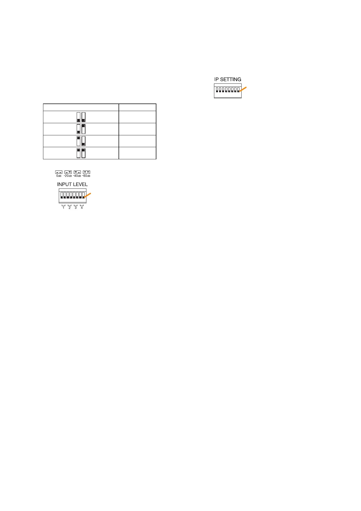
7. Input level setting switch
Each input level of Inputs 1 through 4 are
determined by ON/OFF combination of 2 switches.
You can select one of the following 4 input levels
depending on the input signal level: 0 dB*
2
or
–20 dB*
2
(line level), and –40 dB*
2
or –60 dB*
2
(microphone level). (Factory default setting: 0 dB*
2
)
The table below shows the relationship between
the switch ON/OFF combination and the input
level.
Switch ON/OFF combination Input level
OFF
OFF 0 dB*
2
OFF ON –20 dB*
2
ON OFF –40 dB*
2
ON ON –60 dB*
2
*
2
0 dB = 1 V
(Factory default setting: All set to OFF)
• Switches 1, 2
Used to set the input level of Audio input 1.
• Switches 3, 4
Used to set the input level of Audio input 2.
• Switches 5, 6
Used to set the input level of Audio input 3.
• Switches 7, 8
Used to set the input level of Audio input 4.
Note
Do not touch the input level setting switch during
broadcast.
8. MAC address
This is the MAC address* for the unit. Since
the relationship of each unit location to its MAC
address is established when setting the network
attributes, keep track of this relationship for later
use.
* The unit’s MAC address consists of 12
hyphenated alphanumeric characters.
9. RUN indicator
Continuously ashes when the unit's CPU is
operating normally.
10. IP address setting switch
Sets the unit's IP address.
(Factory default setting: All set to OFF)
• Switch 1
Sets whether to enable or disable IP address
setting by the IP address setting switch.
ON: Enables the IP address set by the IP
address setting switch.
OFF: Disables the IP address set by the IP
address setting switch and enables
the one set using the VX-3000 Setting
Software.
• Switches 2 – 8
Set the IP address by ON/OFF combination of 7
switches. (See p. 3-11.)
Notes
• If you have reset the IP address after power-on,
be sure to restart the unit.
• The IP address setting switch allows the
IP address to be set only in the range of
"192.168.14.51" to "192.168.14.100". If you
wish to set IP address out of this range, set it
using the VX-3000 Setting Software. (See the
separate Setting Software Instructions, "UNIT
DETECTION AND NETWORK SETTINGS.")
OFF
ON
OFF side
Note: Switches 1 through 8 numbered from left to right.
OFF
ON
OFF side
Note: Switches 1 through 8 numbered from left to right.