2-14
Chapter 2
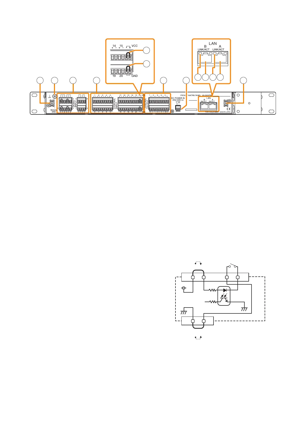
NOMENCLATURE AND FUNCTIONS
[Rear]
12
15
16
17 18
19 20 19 20
13
1411 11
11.Cabletiexture
Pass the cable tie through this xture, then bundle
and secure the cables connected to each terminal
together with the cable tie.
12. Signal ground terminal
Be sure to ground this terminal for surge protection.
Note: This terminal is not for protective ground.
13. Audio input terminals (1 – 8)
Connect audio signals such as audio player.
The Audio input terminals 1 through 4 are
balanced inputs, of which input signal level can
be set by the input level setting switch inside the
front panel.
The Audio input terminals 5 through 8 are
unbalanced inputs, each of which input signal
level is xed as shown below.
Audio input terminals 5 and 6: –20 dB*
Audio input terminals 7 and 8: 0 dB*
* 0 dB = 1 V
Note
The Audio input terminals 5 through 8 are provided
for connecting audio source devices installed in
the equipment rack.
14. Control input terminals (1 – 20)
These terminals receive activation signals from
external equipment to enable external VX-3000
system control.
Note
The "–" (negative) terminals of the Control input
terminals 1 through 20 are interconnected.
15. Power feed jumper
A jumper is installed on the removable terminal
plug by default. Power is supplied from the
unit's inside to the circuit of the Control input
terminals 1 through 20 (14). Detaching this
jumper disconnects the internal power supply,
necessitating an external power supply instead.
(See "Operation of the power feed jumper and the
isolation jumper" illustrated below.)
16. I solation jumpe r
With the jumper installed, "–" (negative) terminals
of the Control input terminals 1 through 20 (14)
are connected to the power supply (Ground).
Detaching this jumper disconnects the "–"
terminals from the unit, isolating the unit.
(See "Operation of the power feed jumper and the
isolation jumper" illustrated below.)
[Operation of the power feed jumper and the
isolation jumper]
VCC
GND
-
+
Power feed jumper
Photocoupler
Internal circuit
Isolation jumper
Control input